We warmly welcome customers each at home and abroad to contact us to negotiate small business, exchange facts and cooperate with us. We specializing within the production of Agricultural Gearbox, PTO Shafts, Sprockets, Fluid Coupling, Worm Gear Reducers, Gears and racks, Roller Chains, Sheave and Pulleys, Planetary Gearboxes, Timing Pulleys, Shaft Collars and even more. Consist of a single 0.5 modulus brass worm gear shaft and a single 20 teeth brass worm gear wheel. The transmission structure of worm shaft is simple, compact, compact volume and light fat. Worm Shaft Z1=1, turn a round of worm gear teeth, can get a substantial transmission ratio, usually inside the energy CAST IRON WORM GEAR REDUCER The transmission is steady, the vibration, affect and noise are small, the reduction ratio is large, the versatility is broad, and it may be applied with numerous mechanical products.
It may get a sizable transmission ratio with single-stage transmission, and features a compact framework. Most versions have superior self-locking overall performance, and may save braking gadgets for mechanical gear with braking requirements. Gears aids us through a mechanism of rotation amongst two axes to generate electrical power. Therefore they, using the assist of rotation following a mechanical theory relevant to physics transfers speed into electrical power. They might be of two sizes, 1 little along with the other huge, adjoining each other using the enable of teeth. The teeth are interlocked and result in rotation. WORM GEAR AND Positive aspects OF WORM GEARS If between two gears one particular is heavier as well as the other lighter it can be noted that the fat gets to be the great factor to lead to friction. In the event the excess weight seems as well heavy rotation may very well be hampered creating inconvenience to move the machine with which these are connected.
Distinctive gears have different teeth. The teeth are in a twisted type or in the straight kind. It is the action of a helical one to radiate movement between two shafts. Whereas the bevel type has teeth based upon conical surface. The shafts are never parallel and intersected sharply in an angle. WORM GEAR Speed REDUCER Marketplace Pace REDUCER FOR Electrical MOTOR Two or 3 reducers can be utilized to type a multi-stage reducer to get an excellent gear ratio. A worm, in industrial parlance, is actually a shaft which has a helical thread. It’s generally a element of the gear that meshes by using a toothed wheel. Worm gears alternatively, are people recognized as worm wheels. Sometime many persons are puzzled using the terms worm, worm gear and worm drive, contemplating that these three suggest precisely the same matter.
Worm gears are crucial particularly when there is certainly a need to cut back the gear size. It is the worm which has the capacity to produce the gear rotate and not the other way all-around. Using the shallow angle about the worm, the gear will not possess the capability to rotate it.
Kinds of worm gear
You can find basically 3 distinctive kinds of worm wheels: the non-throated; single throated; and double throated. Non-throated worm wheels are these that don’t have throats in both the worms as well as gear. Single throated categories are individuals whose gears are throated. Lastly, double throated ones are these with throated worms and gears.
Worm gear characteristics
There are notable traits of the worm wheel. First, it has the capacity to transfer and carry load with utmost accuracy. It is also finest for significant velocity reductions. The efficiency of your worm gear, having said that, depends upon set up ailments, the worm’s lead angle, sliding speed, surface good quality and lubricant variety.
Building worm gears come to be helpful
A course of action recognized as double enveloping helps make worm gearing grow to be more productive. This technological innovation enhances the existing capabilities of your worm wheel. This leads to better accuracy and enhanced torque. What can make the approach so particular is definitely the fact that it might be made use of to produce improved lubrication and style when loads are divided in every with the gear’s teeth. Worm gear applications
Worm wheels make conveyor programs do its perform. Conveyors are tools to transfer one particular material from one particular location to an additional. Aside from conveyor methods however, the worm wheel may also be used in high efficiency motor vehicles.
Hollow Pin Chains 08BP 40HP, 50HPSS, 60HP, 12BHP, 80HP, C2040HP, C2050HP, C2060HP, C2080HP, HB50.8, C2042HP, C2052HP, C2062HP, C2082HP, C2042H-HP, C2052H-HP, C2062H-HP, C2082H-HP Stainless Steel Roller Chain Stainless Steel Conveyor Chain Stainless Steel Roller Chains,Stainless Steel Conveyor chain, Stainless steel chain for bottle conveyor line that’s applied on bottle filling conveyor lines, other typical ss chain or specific ss chains (SS304 chain, SS316 chains, SS316L chains, SS conveyor chains, SS304 conveyor chain, SS316 conveyor chain) all available Rust 304 Stainless Steel Chain/Lifting Chain Rigging Hardware, Over Thousands Wide range. Like Connecting Website link, Safety Hook, Eye Hook, Clevis Hook, Master Hyperlink, Master Website link Assembly, And so forth. Series Zinc plated Agricultural Transmission Chain for Feeder household Clear Grain Attachment: K1, K5, K19, K30, K39, 220B, F4, F5, F14, F45, G18, TM91E, TM92, C6E, C11E, C13E, C30E, CPE, LV41N, Surface Remedy: Shot-Peening, Zinc plated. Application: broadly utilized in Feeder home, Clear Grain, Return Grain in agricultural machine. CC600 Corrosion Resisting Cast iron Chain Our CC 600 Conveyor chains are produced in malleable iron with steel pins, with pins that are unhardened. This confirmed layout results in an assembled chain that is definitely extremely sturdy and wear resistant. Made withing the fuel bottling marketplace (Specifically Liquid Petroleum Fuel ) our CC600 series remains a products of first choice for distributors and end customers alike, the place a top quality product is needed initial time, every single time. The CC600 chains are meant for use in multistrand conveyors handling individual loads underneath disorders of mild corrosion. They may be normally supported in channels and are really versatile, making it possible for for fluid motion and versatility when essential. This versatility lets them to get utilized within a selection of heavy duty applications but their key application is during the bottling marketplace where these are referred to as on to deal with crates and fuel bottles. focuses on making all varieties of mechanical transmission merchandise and hydraulic transmission products, such as planetary gearboxes Chains are series of linked back links or rings which might be normally made of metal and may be linked or fitted into one another. Each and every piece of the chain can have over one particular link dependent on its application. Some employs of chains is often for fastening, binding or supporting objects. The two most common designs of making chains are roller chains and those that are torus shaped. The type of the chain is determined by the application on the chain. Torus shaped chains are incredibly popular in many applications. They’re able to be utilised for hoisting, securing or supporting and have an incredibly easy form of rings which are connected to each other. This uncomplicated layout gives these chains flexibility in two dimensions. Their simple design and flexibility make it possible for them to get made use of for a lot of tasks this kind of as securing a bicycle
Roller chains are very common in bicycles. They’re designed to transfer energy in machines. Taking bicycle chains for example, they can be created to mesh using the teeth of the sprockets in the machine. Flexibility in these chains is also restricted because they can only move in one direction. Some popular applications of chains is often as important chains, snow chains and bicycle chains. As stated earlier within this posting, bicycle chains are roller chains. They transfer power from pedals to your drive-wheel that in turn propels the bicycle forward. These chains are ordinarily manufactured from plain carbon or an alloy of steel nonetheless some may be nickel-plated to be able to prevent rust. These chains can also be deemed to get extremely vitality productive. Even though lots of people might count on the efficiency for being enormously affected by the lubricant, a examine that was carried out in a clean laboratory uncovered that in lieu of lubricants, a bigger sprocket would present a much more effective drive. Also, the greater the tension while in the chain, the much more efficient it would be.
single row four point get in touch with ball slewing rings is composed of two seat rings, which style and design in compact construction and light bodyweight, steel ball make contact with together with the circular raceway at 4 points; it might bear the axial force, radial force and the tilting moment at the exact same time. Coresun drive Single-row four stage contact ball ring has the features of compact in style, and light in excess weight. The balls roll within the circular race at 4 points, so it might undertake the axial force, radial force and tipping minute in the exact same time. This series of four stage get hold of ball bearings are ideal in lots of engineering machinery, which include rotary conveyor welding operation machine, modest cranes, tiny and medium-sized excavators,slewing conveyer, welding manipulator, light and medium duty crane, and also other construction machinery. Three varieties of this type of single row 4 level speak to ball slewing bearing: A. With out gear bearing (non tooth) B. External gear bearing (external tooth) C. Internal gear bearing (internal tooth)
double row different diameter ball slewing bearing is mostly created up of in-up ring, in-down ring and outside ring, so balls and spacers might be immediately discharged into the upper and lower raceway. In line with worry problems, bearings are arranged to two rows of balls of various diameter. This assembly is extremely handy. Angle of the two upper and reduce raceway is 90??so bearings can bear substantial axial force and resultant torque. Bearing demands specific design when radial force is 0.one instances greater than the axial force. Large in sizes and functions compact in style and design, bearings are especially application in handling equipments requiring medium above diameter, including tower crane and mobile crane.
single row cross roller slewing ring is mostly manufactured up of inside and outside rings. It attributes compact in layout, light in bodyweight, little in assembling clearance, and higher in putting in precision. As the rollers are crossed arranged by one:1, it is actually suitable for high precision mounting and capable to bear axial force, radial force and resultant torque simultaneously. This series single row crossed roller slewing bearing have widely application in lift transport aircraft, building machinery, and military merchandise. one. Skilled gears producer two.Experienced in Cooperate with big Companies 3. Skilled gears Engineering Capability four.Steady gears High quality five.Reasonable gears Costs six.Small gears Orders Accepted 7.Continuous gears high-quality improvements eight. Large gears high quality Overall performance 9.Brief gears lead time and shipment 10.Specialist gears service We are able to develop six models of slewing bearings in a variety of specifications with diameters ranging from 400 mm to 5050 mm. Our products show every day to become critical structural and connection components utilized in wind turbines, excavators, mobile cranes, harbor and shipyard cranes, robots, health care scanners and generally mechanical engineering. Top quality Manage: Good quality is the vital to our good results. We’re committed to achieving customers’ satisfaction by supplying high-quality services and products. We ensure that our complete high quality management system is in accordance with ISO9001 regular and it is performed successfully. In pursuit of high-quality raw resources, we go through a stringent verification and selection method to choose the very best suppliers of forged rings and other elements in China. If required, we will also apply further large-diameter forged rings created by ThyssenKrupp in Germany. Cranes are uniquely constructed, which means the slewing ring bearing is definitely an important element of its style. Good quality and precision during the manufacturing procedure. Gear transmission refers to your gadget that transmits movement and electrical power through the gear pair. It is the most broadly employed mechanical transmission process in contemporary gear. Its transmission is much more accurate, high efficiency, compact construction, dependable operation and prolonged services existence.Our gears is often heat taken care of, hardened, oil immersed as outlined by consumer requirements.The gear is broadly utilized in field, car, power resources, motor, bicycle, electrombile.
Nylon gear racks is made use of on sliding gate, There exists steel core within it. we exported to Europe in huge quantity. There may be steel core inside the nylon gear rack.You will find two goods accessible. There are actually 4 eye(four bracket is light style) and six eyes(six brackets is heavy style).Every single piece of nylon gear rack with screw set Manufacturer supplier exporter of gear rack We exported gear rack in significant quantity to Europe, America, Australia, Brazil, South Africa, Russia etc. There is normal gear rack readily available and in addition special gear rack as per your drawing or samples. Our gear racks produced by CNC machines There’s quite a few sizes of steel gears rack for sliding door also. M4 8?¨¢30, M4 9?¨¢30, M4 10?¨¢30, M4 11?¨¢30, M4 12?¨¢30, M4 20?¨¢20, M4 22?¨¢22, M6 30?¨¢30 and so on For M4 8?¨¢30, M4 9?¨¢30, M4 10?¨¢30, M4 11?¨¢30, M4 12?¨¢30, 1M length have three bolt,nut, washer sets and each 4pcs or 6pcs packed into carton box then put into steel pallet. For M4 8?¨¢30, M4 9?¨¢30, M4 10?¨¢30, M4 11?¨¢30, M4 12?¨¢30, 2M length have 4 bolt,nut, washer sets. We are able to also supply the sliding gate aspect this kind of as sliding door pulley, wheel, roller and so forth. Please kindly test and allow me know your detail request When you need to have 2M or 3M, or every other length, we can make as per your requests Nearly all of our purchaser will send us drawing and we will develop as per your drawing or sample. We make Module M1-M8 racks, CP and DP British regular racks. The utmost length in the rack is 2 meters. Our products are widely used in lots of fields such as automatic doors, window openers, engraving machines, lifters, escalators, automated warehousing, foods machinery, electrical power equipment, machine resources, precision transmission, and so forth.
We exported gear rack in huge amount to Europe, America, Australia, Brazil, South Africa, Russia and so forth. There is certainly conventional gear rack offered and in addition unique gear rack as per your drawing or samples. Our gear racks generated by CNC machines.
Our gear racks are made use of for window machine, engraving machine, lift machine, opener rack, CNC machine, car, industrial usage so on. 1) Our gear rack is made as per DIN specifications by CNC machine 2) The stress angle: 20??/14.5?? 3) Module: M0.4-M36/DP1-DP25 four) The utmost length can be 3500mm 5) The material is often Q235, C45, SS304, SS316L, aluminum, copper, nylon and so forth. Our gear racks are applied for window machine, engraving machine, lift machine, opener rack, CNC machine, automobile, industrial utilization so on. Industrial Gear Rack Lorem ipsum dolor sit amet, consectetur adipiscing elit, sed do eiusmod tempor incididunt ut labore et dolore magna aliqua.
We will also supply Development lift gear rack,American common gears racks,steel gear rack,helical gear rack,flexible gear racks,power steering rack,steering gear rack ,stainless steel gear rack ,round rack gear ,nylon gear rack ,spur gear rack ,boston gear rack ,audia gear rack ,gears racks ,rack and pinion gear 1. Rich business encounter since 1988. two. Wide organize products line, which include plastics sheet/rod/parts/accessories: MC NYLON, OIL NYLON, POM, UHMW-PE, PU, PETP, Pc, PTFE, PVDF, PPS, PEEK, PAI, PI, PBI ect. 3. Manufacture, style and processing service as per your demand one. Superior Tensile power; 2. High impact and notching effect strength; 3. Higher heat deflection temperature ; four. High strength and stiffness; 5. Fantastic glide and limp house characters; six. Fantastic chemical stability against natural solvents and fuels; 7. Resistant to thermal aging (applicable temperature concerning -50??C and 110??C; 8. Dimension alternation by humidity absorption must be regarded as;
Shaft sleeve, bearing bush, lining, lining plate, gear; Worm gear, roller copper guide rail, piston ring, seal ring, slide block; Spheric bowl, impeller, blade, cam, nut, valve plate, Pipe, stuffing box, rack, belt pulley, pump rotor, and so on.rack pinion gear for elevator in stockoperator Steel and Nylon gear rack SPUR GEAR RACK AND PINION nylon gear rack iron gear rack We warmly welcome consumers the two at your home and abroad to speak to us to negotiate organization, exchange data and cooperate with us.
IN CNC GEAR Manufacturing PLANT, Over 10 OF GEARS Generating LINES: Gear turning,hobbing,shaving,shaping,grinding,slotting, broaching , we?¡¥ve made significant investment..
Our large precision equipment can retain a high excellent prodcuts.CAN DO Every one of the HEATING Method: CARBURIZING/CARBONITRIDING/QUENCHING/NORMALIZING/ANNEALING/REHEATING two sets of UBE series multi-purpose chamber(IQ) Japan furnace; 2 sets of German Ipsen ambiance furnace lines.
9 ton of steel capacity for heat therapy a day. Low CARBON STEEL METAL GEARS Modest,Tiny STEEL METAL SPUR GEARS! From straightforward 2-axis turning to 7-axis, turn-mill-drill CNC Swiss-type machines, we’re outfitted having a complete line of CNC gear from your following manufactures: molding machines/ stamping machines automatic lathe machines/ spring machines. Surface: as your necessity OUR CLEANSES one.Materials:C 45# steel ,stainless steel or other needed resources. two.Sprockets is often created according the customer?¡¥s drawings Our principal items: Ultra higher molecular excess weight polyethylene, MC nylon, PA6, POM, HDPE, PP,PU, Computer, PVC, ABS, ACRYLIC,PTFE, PEEK, PPS,PVDF. 3.Heat treatment: Hardening and Tempering, Substantial Frequency Quenching, Carburizing Quenching and so on according the specifications..
4. Inspection: All things are checked and tested totally during just about every functioning procedure and following manufacturing will probably be reinspected. Gear transmission refers towards the gadget that transmits movement and power in the gear pair. It is actually quite possibly the most extensively utilised mechanical transmission process in modern day products. Its transmission is a lot more exact, high efficiency, compact framework, dependable operation and lengthy service existence.
Our gears could be heat taken care of, hardened, oil immersed according to buyer desires.
The gear is broadly made use of in business, automobile, electrical power equipment, motor, bicycle, electrombile. Substantial PRECISION Custom SPUR HELICAL GEAR Spur gears are widely accepted since the most productive sort of gearing resolution, once the application of transmitting power and uniform rotary movement from a single parallel shaft to yet another is required. Determined from the center distance, spur gears produce a steady working velocity drive. This drive pace may be decreased or enhanced from the variable quantity of teeth that exist within the driving gear. Form: BEVEL GEAR Manufacturing Approach: Minimize Gear Toothed Portion Form: Bevel Wheel Major Consumer: Electrical instrument factory Export Markets: International Modest PINION STEEL DOUBLE SPUR GEAR Zn-plating, Ni-plating, Cr-plating, Tin-plating, copper-plating, the wreath oxygen resin spraying, the heat disposing, hot-dip galvanizing, ELECTROPLATING, ANODIZING And so forth. Black oxide coating, painting, powdering, colour zinc-plated, blue black zinc-plated, rust preventive oil, titanium alloy galvanized, silver plating, plastic,We are able to make customers?¡¥ satisfactory goods according on the samples or drawings presented by clients. To the completion of a product or service, we also require to understand his materials, heat remedy needs and surface therapy necessities. We’re a factory with 40 many years of manufacturing working experience, welcome to consult. we use the newest machining engineering by using a wide range of capabilities to meet your demands. Our manufacturing amenities consist of 3-5 axis milling, lathes, grinding, and so forth, and state from the artwork metrology. With these machines, we develop complex components within the most productive and exact way. Our manufacturing abilities let us to produce your element from prototype to mass production to the most precise of jobs. gear box,gearbox,automated gearbox,gearbox components,gearbox repairs,steering gear box,reduction gearbox,worm gear,motor gearbox,car or truck gearbox,gearbox store,worm gear box,gearbox suppliers,box gear,planetary gear box,modest gearbox,helical gearbox,dc gear motor,gear motor,gear reducer,helical gear box,car gear box,gearbox gears,transmission gearbox,reduction gear box,planetary gear,gearbox transmission,car or truck transmission,utilized gearbox for sale,worm gear motor,made use of gearbox,worm gear reducer,transmission gears,planetary gear reducer,substitute gearbox,mini gearbox
PTO is actually a splined drive shaft which is generally placed on tractors or could be made use of to provide electrical power backup to a separate machine.
The PTO shafts that we supply comprises of two carden joints and telescopic couplings. Tractor side and put into action side are the two ends of those shafts. The employ side includes a shear bolt kind yoke and includes safety guards. 1, Material: Carbon steel/ stainless steel/ aluminum alloy/ copper/bronze/iron/etc.
2, OEM or as per sample or drawing
3, Surface: Blacking, Polishing, Anodize, Chrome plating, Zinc plating, Nickel plating, Tinting, Energy coating and so forth.
4, Procedure: Forging, Stamping, Machining, Metalworking, Sheet Metal Bending, Surface Therapy, Heat Therapy, Gridding, Milling, wire EDM, Linear Cutting and so forth.
five, Precision: OEM/ODM is accessible The energy take-off (PTO) is a sophisticated mechanism, allowing implements to draw power from your engine and transmit it to yet another application. It works being a mechanical gearbox which could be mounted over the vehicle?¡¥s transmission. CHINA FACTORY LARGEBRASS MILLING AND ALUMINUM CASTING MOLDS Manufacturer We’re the producer to produce Japanese tractor spare components,primarily for kubota,iseki,yanmar,and so forth. We are supplying and exporting Japanese tractor elements as the following versions ¡§C Kubota model: B5000, B7000, B1400, B1600 ¡§C YM model: YM F14, YM1100, YM F1401/1901,YM F35 ¡§C Iseki model: TX1300, TX1410,TU1400-1500 UNIVERSAL JOINT MECHANICAL COMPORENTS MACHINE TRACTOR PTO SHAFT Components UNIVERSAL JOINT Tubes or Pipes
We?¡¥ve by now received Triangular profile tube and Lemon profile tube for each of the series we provide.
And we have now some star tube, splined tube as well as other profile tubes but only for a sure sizes. We specializing within the production of Agricultural Gearbox, PTO Shafts, Sprockets, Fluid Coupling, Worm Gear Reducers, Gears and racks, Roller Chains, Sheave and Pulleys, Planetary Gearboxes, Timing Pulleys, Shaft Collars and more. 5 Finish yokes
We have got 13 varieties of splined yokes and eight kinds of plain bore yokes. I’ll suggest the normal type for your reference.
You can also send drawings or pictures to us for those who can’t discover your item in our catalog.
six Safety units or clutches
I’ll attach the specifics of security devices for your reference. We have presently have Absolutely free wheel (RA), Ratchet torque limiter(SA), Shear bolt torque limiter(SB), 3types of friction torque limiter (FF,FFS,FCS) and overrunning couplers(adapters) (FAS).
7 For almost any other a lot more exclusive needs with plastic guard, connection approach, shade of painting, bundle, and so forth., please really feel totally free to let me know. The Gearboxes are developed for connecting gear pumps to farm tractor energy take offs (PTO). Output velocity of power get offs is 540rpm which can be in contrast with the correct operating speeds of hydraulic pumps. Various input operating speeds can also be ideal,offered that the PTO gearbox output speed will not exceed 3000 rpm. Housing Produced in shell-cast aluminum or in high mechanical resistance cast iron. Torques The torque figures described from the technical charts of all of the PTO Gearboxes refer to steady duty cycles. Torques under intermittent doing work situations is often exceeded by 20%. Maintenance Please verify the oil degree by way of the special oil window every 50 hrs. Operating temperatures ought to not exceed 120 degrees celcius under continuos duty cycle. one. Tubes or Pipes We have by now received Triangular profile tube and Lemon profile tube for the many series we deliver. And we have now some star tube, splined tube and other profile tubes required by our consumers (for any sure series). (Please notice that our catalog doesnt include all the objects we produce) If you would like tubes besides triangular or lemon, please provide drawings or pictures.
two.End yokes We have received many forms of rapid release yokes and plain bore yoke. I will recommend the normal kind for your reference. It is possible to also send drawings or photographs to us in case you can not obtain your item in our catalog.
3. Safety products or clutches I will attach the specifics of security gadgets for the reference. We have already have Free of charge wheel (RA), Ratchet torque limiter(SA), Shear bolt torque limiter(SB), 3types of friction torque limiter (FF,FFS,FCS) and overrunning couplers(adapters) (FAS).
four.For just about any other much more exclusive requirements with plastic guard, connection method, colour of painting, package, and so on., please really feel free of charge to allow me know.
Functions: one. We’ve got been specialized in developing, manufacturing drive shaft, steering coupler shaft, universal joints, which have exported to your USA, Europe, Australia etc for a long time 2. Application to all kinds of standard mechanical situation 3. Our merchandise are of high intensity and rigidity. four. Heat resistant & Acid resistant 5. OEM orders are welcomed The Gearboxes are made for connecting gear pumps to farm tractor energy take offs (PTO).Output speed of electrical power take offs is 540rpm which can be compared with the right working speeds of hydraulic pumps.Distinctive input working speeds can also be appropriate,offered the PTO gearbox output speed will not exceed 3000 rpm.
Gears Created in Steel UNI 18 PCR M03.Stub teeth guarantee very substantial resistance and run very quietly.
Shafts Manufactured in steel UNI 16 CRN4.They are coupled with splined gears and are built to stand the torque values stated from the catalogue.
Lubrication 90 gear oil must be put within the pto gearbox prior to use, change the oil after the first 60-80 hrs and then each and every 12 months or 1500 hours which ever falls first.
Servicing Please test the oil level by means of the distinctive oil window every 50 hours.Functioning temperatures should really not exceed 120 degrees celcius below continuos duty cycle.
We specializing from the manufacturing of Agricultural Gearbox, PTO Shafts, Sprockets, Fluid Coupling, Worm Gear Reducers, Gears and racks, Roller Chains, Sheave and Pulleys, Planetary Gearboxes, Timing Pulleys, Shaft Collars and even more. Taper Lock Pulley V Belt Pulley We present high top quality Taper Lock Pulley V Belt Pulley in competitive price v pulley, v belt pulleys, taper lock pulley,v belt pulleys ,v pulley,v groove pulleys,v groove belt pulley,taper lock pulley,taper lock v belt pulleys,taper lock vpulley bushing pulley,taper lock pulleys/ taper bore pulley,substantial v belts pulley,double v belts pulley,cast iron v belt pulleys belt pulley,variable velocity v belt pulley,v belt pulley split pulley,cast iron v belts pulley V-BELT PULLEY INTRODUCE: V- belt pulley of different forms ( in line with type and width of belts). The material utilised is cast iron EN-GJL-250 UNI EN 1561, and for only a handful of sorts it really is steel C45 E UNI EN 10083-1. They’ve got a tiny prebore that may be machined as outlined by customers?¡¥ needs. Also one of the most widespread types can be found also with taperlock bore. V BELT PULLEY Specs a) Vbelt pulley for taper bushing: SPZ, SPA, SPB, SPC b) Adjustable velocity V-belt pulleys and variable speed pulleys c) Flat belt pulleys and conveyor belt pulleys ?¡è AMERICAN Standard: a) Sheaves for taper bushing: 3V, 5V, 8V b) Sheaves for QD bushings: 3V, 5V, 8V c) Sheaves for split taper bushing: 3V, 5V, 8V ?¡è We are able to Give THE RANG Size DIAMETER 62MM~2000MM d) Sheaves for 3L, 4L or perhaps a, and 5L or B belts: AK, AKH,2AK, 2AKH, BK, BKH,2BK, 2BKH, 3BK e) Adjustable sheaves: poly V-pulley, multi-pitch H, L, J, K and M Quality Timing Pulley Light Excess weight Industrial Nylon Plastic Pulley V Belt Pulley one.Materials: Aluminium alloy,Carton steel, Cast iron, Stainless steel timing belt pulleys 2.Surface treament: Anodizing, Blackening, Zinc Plating, Phosphatiing 3. Teeth Quantity from 9 to 216; O.D. from 10mm to 1000mm; four. Timing belt pulleys MXL, XL, L, H and XH; T2.five, T5, T10, AT5,AT10; 3M,5M,8M and 14M S3M, S5M, S8M, 14MGT, 8MGT, RPP8M 5. Taper bush and polit bores 6. Timing pulley bar 3M,5M,8M,MXL,XL,L T2.five T5 T10 AT5 and AT10 1) Strong design and style, appropriate for hefty lifting. 2) The bearing housing and steel tube are assembled and welded with a concentric automatic. automobile four) The bearing finish is constructed to guarantee the roller shaft and bearing is often firmly linked. air compressors 6) Roller and supporting components/materials are manufactured to DIN/ AFNOR/ FEM/ ASTM/ CEMA regular. belt conveyor drive drum pulley About roller,we can make gravity conveyor roller,steel conveyor roller,driving roller,light middle duty conveyor roller,o-belt tapered sleeve roller,gravity tapered roller,polymer sprocket roller and so forth. Additional information, please get in touch with us. Can be used for tractors 3) Cutting of your steel tube and bearing is performed using the use of a digital car device/machine/equipment.. garden cutter five) Fabrication with the roller is effected by an auto device and 100% examined for its concentricity. welcome your inquiries 7) The casing is produced with highly composite, anti corrosive alloy. one) European specifications : a) V-belt pulley for taper bushing: SPZ, SPA, SPB, SPC; up to ten grooves
b) Adjustable speed V-belt pulleys and variable speed pulley
c) Flat belt pulleys and conveyor belt pulleys
2) American standards:
a) Sheaves for taper bushing: 3V, 5V, 8V
b) Sheaves for QD bushings: 3V, 5V, 8V
c) Sheaves for split taper bushing: 3V, 5V, 8V
d) Sheaves for 3L, 4L or even a, and 5L or B belts: AK, AKH, 2AK, 2AKH, BK, BKH,2BK, 2BKH, 3BK
e) Adjustable sheave: poly V-pulley, multi-pitch H, L, J, K and M Why Select Us 1) Knowledge in casting for more than 15 many years and served customers all about the planet. 2) Common material according to technical drawing three)Steady high quality 4) On-time delivery five) Aggressive selling price and great service 6) Good consumer suggestions from domestic and international marketplace seven) International advanced-level equipment including CNC, numerical lathes, furnance, welding equipment, CMM and detect &testing equipment we used to make certain our product?¡¥s quality. 8) OEM support, your demand is our pursued. 9) ISO9001:2008 and TS16949 excellent control 10) Standard: ASTM BS DIN etc
Bush Chains As one of main motor coupling manufacturers, suppliers and exporters of mechanical merchandise, We give bush chains and lots of other goods. Manufacturer supplier exporter of bush chains We specializing inside the production of Agricultural Gearbox, PTO Shafts, Sprockets, Fluid Coupling, Worm Gear Reducers, Gears and racks, Roller Chains, Sheave and Pulleys, Planetary Gearboxes, Timing Pulleys, Shaft Collars and even more. We have now exported our solutions to clientele about the world and earned a superb reputation simply because of our superior merchandise excellent and after-sales service. We warmly welcome consumers both in your house and abroad to get in touch with us to negotiate small business, exchange facts and cooperate with us. we are one particular expert chain factory ,producing both common roller chains and nonstandard chains,A and B series roller chain,straight side roller chain,H series of roller chain, motocycle chain ,other roller chain . Zinc-plated,Nickel-plated,Docromet-plated etc.Comply using the regular of ANSI,ISO,DIN,BSetc.as well as with diverse attachment. High-quality could be assured! Our merchandise have passed ISO:9001 good quality management procedure and stand the end users?¡¥ ordeal. We devote ourselves to manufacture the high-quality solutions with aggressive charges, we know the industries nicely, consequently from layout to materials choice, until manufacturing system is up to the substantial normal, meanwhile our arranging staff and worldwide staff will ensure the punctual delivery. Timing Bush Chains for Automobile Engine 1. Material: Stainless steel / Alloy steel / Produced to order two. Surface Remedy: Zinc-Plated / Nickel-Plated / Shot Peening / Blackening three. Chain Variety: Roller chains, Drive chains,Conveyor Chains, Hollow Pin Chains,Welded chains, Steel Pin Chains, Palm oil chains,Sugar Mill Chains.ect. Transmission Precision Bush Chains A lifting chain is rigging products utilized with hoists, cranes, and winches in material managing applications. An arrangement referred to as a chain sling is usually made use of because the lifting element connecting the hoisting gadget on the load. A chain sling consists of a master website link and one or much more chain legs with hooks. Transmission Precision Roller and Bush Chains Applied industrial transmission roller chains;Industrial and agricultural machinery, together with conveyors,wire¡§C and tube¡§Cdrawing machines, printing presses, cars, motorcycles, and bicycles.It includes a series of short cylindrical rollers held with each other by side links.It really is a straightforward, trustworthy, and productive signifies of electrical power transmission. Good quality orientation: Above the common, largely exported to USA, Europe, Asia etc. Strictly in accordance: ISO/ANSI/DIN regular. Price tag orientation: Price-performance ratio is incredibly substantial. Stainless Steel Hollow Pin Bush Chains Conveyor Chain Roller transmission bush double flex chain Side Bow Chain The Sleeve Chain/ Bush Chain/motorcycle chain substantial strength bucket elevator conveyor bush roller chain We’re skilled supplier of chains Multi strand sizes available; up to five strand, for decide on size normal attachment accessible ten.Chains from 04b~16b are with spring clip, other are riveted; cottered layout is obtainable for dimension 80 to 240 Stainless steel chain and nickel plated chains is obtainable; particular layout also readily available (i.e., oven conveyor) and we can generate as per materials your requests, ordinarily stainless steel chains materials is SS304, when you need to have SS316 or SS316L etc. it truly is accessible too This bush chain that has a lowered amount of parts, has proved for being notably successful in substantial duty, substantial abrasion application in which lubrication is just not possible. Our steel bush chains happen to be proving efficiency in mill duty centrifugal discharge elevators inside of the more difficult applications encountered during the cement market.
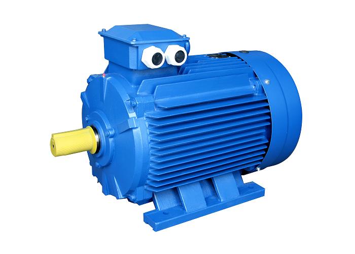
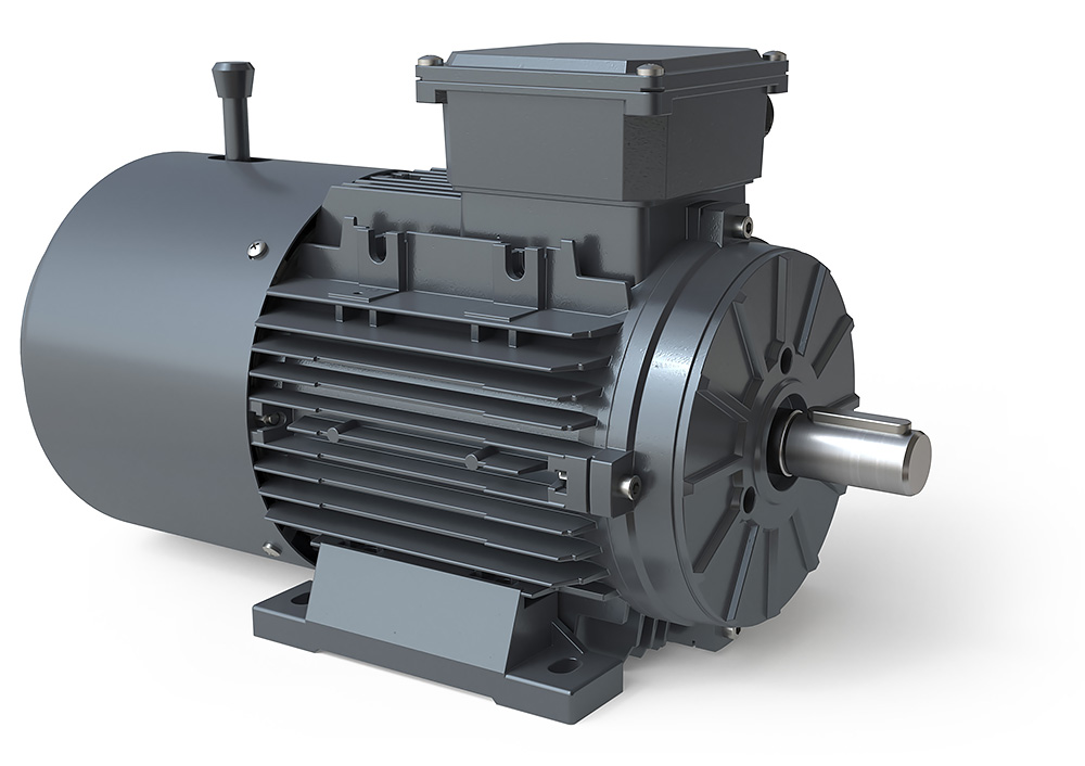
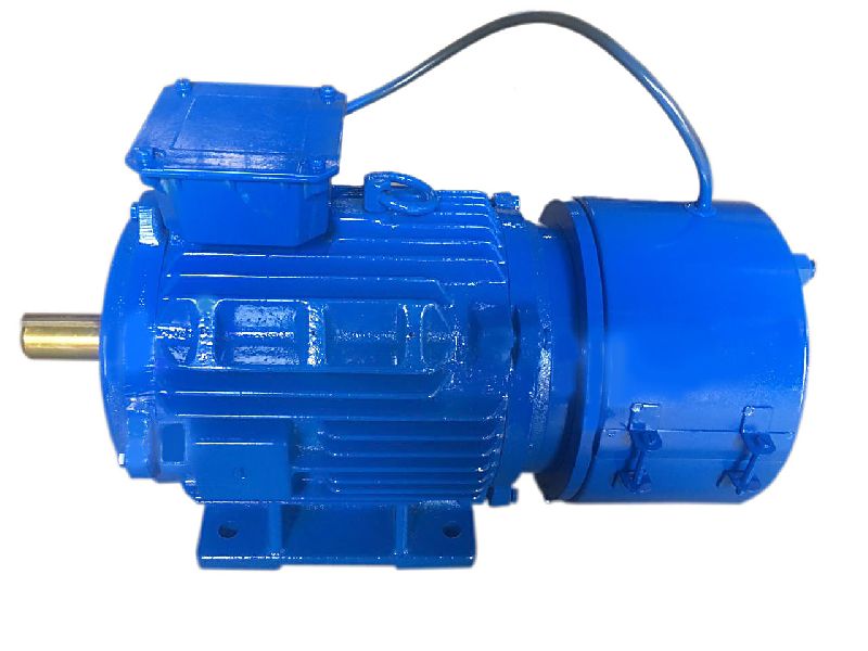
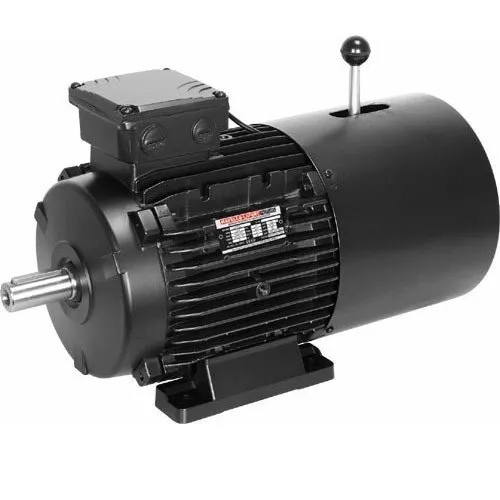
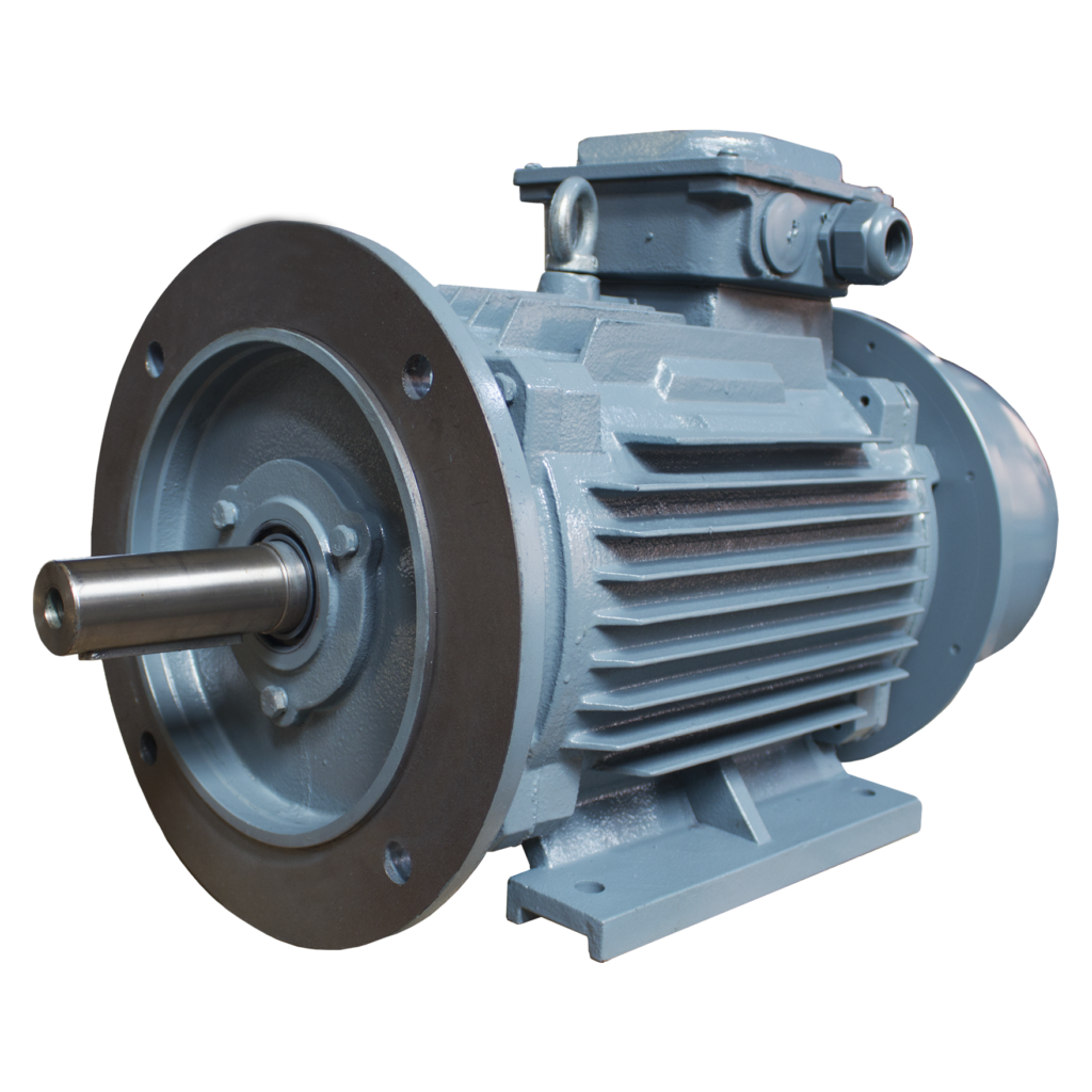
YEJ2,YDEJ2 SERIES ELECTROMAGNETIC BRAKE THREE PHASEELECTRIC MOTOR
The YEJ2 and YDEJ2 series electromagnetic brake motors are upgraded versions of the YEJ series, meeting JB/T6456 standards and having electrical performance similar to the Y2 series. They are widely used in various machinery.
Center height of frame
63~225mm
Power range
0.12~45kW
Rated voltage
380V(or order)
Rated frequency
50HZ(or 60Hz)
Insulation class
F
Protection class
IP 55
If you want more information, please consult me
Product Parameters
Detailed Photos
Our Advantages
Packaging & Shipping
Company Profile
FAQ
Q: Do you offer OEM service? A: Yes, we can customize it as your request.
Q: What is your payment term? A: TT. LC, AND WESTER UNION
Q: What is your lead time? A: About 30 days after receiving deposit.
Q: What certificates do you have? A: We have CE, ISO. And we can apply for specific certificate for different country such as SONCAP for Nigeria, SASO for Saudi Arabia, etc
Q: What about the warranty? A: We offer 12month warranty period as the quality guarantee.
Q:What service do you offer? A: Pre-sales service, in-sales service, after-sales service. If you become our local distributor, we can introduce end-customers to purchase from you.
Q:What’s your motor winding? A: 100% copper winding
Q:Which port is near to you? A: HangZhou port. And we can arrange to deliver HangZhou, ZheJiang , Urumqi, or other Chinese cities, too.
Q:Could you offer CHINAMFG Certification. A: we can do as your request.
/* January 22, 2571 19:08:37 */!function(){function s(e,r){var a,o={};try{e&&e.split(“,”).forEach(function(e,t){e&&(a=e.match(/(.*?):(.*)$/))&&1
Application:
Industrial
Speed:
High Speed
Number of Stator:
Three-Phase
Function:
Driving
Casing Protection:
Protection Type
Number of Poles:
4pole
Samples:
US$ 500/Piece 1 Piece(Min.Order)
|
Customization:
Available
|
What advancements in brake motor technology have improved energy efficiency?
Advancements in brake motor technology have led to significant improvements in energy efficiency, resulting in reduced power consumption and operational costs. These advancements encompass various aspects of brake motor design, construction, and control systems. Here’s a detailed explanation of the advancements in brake motor technology that have improved energy efficiency:
High-Efficiency Motor Designs: Brake motors now incorporate high-efficiency motor designs that minimize energy losses during operation. These designs often involve the use of advanced materials, improved winding techniques, and optimized magnetic circuits. High-efficiency motors reduce the amount of energy wasted as heat and maximize the conversion of electrical energy into mechanical power, leading to improved overall energy efficiency.
Efficient Brake Systems: Brake systems in modern brake motors are designed to minimize energy consumption during braking and holding periods. Energy-efficient brake systems utilize materials with low friction coefficients, reducing the energy dissipated as heat during braking. Additionally, advanced control mechanisms and algorithms optimize the engagement and disengagement of the brake, minimizing power consumption while maintaining reliable braking performance.
Regenerative Braking: Some advanced brake motors incorporate regenerative braking technology, which allows the recovery and reuse of energy that would otherwise be dissipated as heat during braking. Regenerative braking systems convert the kinetic energy of the moving equipment into electrical energy, which is fed back into the power supply or stored in energy storage devices. By harnessing and reusing this energy, brake motors improve energy efficiency and reduce the overall power consumption of the system.
Variable Speed Control: Brake motors equipped with variable frequency drives (VFDs) or other speed control mechanisms offer improved energy efficiency. By adjusting the motor’s speed and torque to match the specific requirements of the application, variable speed control reduces energy wastage associated with operating at fixed speeds. The ability to match the motor’s output to the load demand allows for precise control and significant energy savings.
Advanced Control Systems: Brake motors benefit from advanced control systems that optimize energy usage. These control systems employ sophisticated algorithms and feedback mechanisms to continuously monitor and adjust motor performance based on the load conditions. By dynamically adapting the motor operation to the changing requirements, these control systems minimize energy losses and improve overall energy efficiency.
Improved Thermal Management: Efficient thermal management techniques have been developed to enhance brake motor performance and energy efficiency. These techniques involve the use of improved cooling systems, such as advanced fan designs or liquid cooling methods, to maintain optimal operating temperatures. By effectively dissipating heat generated during motor operation, thermal management systems reduce energy losses associated with excessive heat and improve overall energy efficiency.
These advancements in brake motor technology, including high-efficiency motor designs, efficient brake systems, regenerative braking, variable speed control, advanced control systems, and improved thermal management, have collectively contributed to improved energy efficiency. By reducing energy losses, optimizing braking mechanisms, and implementing intelligent control strategies, modern brake motors offer significant energy savings and contribute to a more sustainable and cost-effective operation of equipment.
What maintenance practices are essential for extending the lifespan of a brake motor?
Maintaining a brake motor properly is crucial for extending its lifespan and ensuring optimal performance. Regular maintenance practices help prevent premature wear, identify potential issues, and address them promptly. Here are some essential maintenance practices for extending the lifespan of a brake motor:
Cleanliness: Keeping the brake motor clean is important to prevent the accumulation of dirt, dust, or debris that can affect its performance. Regularly inspect the motor and clean it using appropriate cleaning methods and materials, ensuring that the power is disconnected before performing any cleaning tasks.
Lubrication: Proper lubrication of the brake motor’s moving parts is essential to minimize friction and reduce wear and tear. Follow the manufacturer’s recommendations regarding the type of lubricant to use and the frequency of lubrication. Ensure that the lubrication points are accessible and apply the lubricant in the recommended amounts.
Inspection: Regular visual inspections of the brake motor are necessary to identify any signs of damage, loose connections, or abnormal wear. Check for any loose or damaged components, such as bolts, cables, or connectors. Inspect the brake pads or discs for wear and ensure they are properly aligned. If any issues are detected, take appropriate action to address them promptly.
Brake Adjustment: Periodically check and adjust the brake mechanism of the motor to ensure it maintains proper braking performance. This may involve adjusting the brake pads, ensuring proper clearance, and verifying that the braking force is sufficient. Improper brake adjustment can lead to excessive wear, reduced stopping power, or safety hazards.
Temperature Monitoring: Monitoring the operating temperature of the brake motor is important to prevent overheating and thermal damage. Ensure that the motor is not subjected to excessive ambient temperatures or overloaded conditions. If the motor becomes excessively hot, investigate the cause and take corrective measures, such as improving ventilation or reducing the load.
Vibration Analysis: Periodic vibration analysis can help detect early signs of mechanical problems or misalignment in the brake motor. Using specialized equipment or vibration monitoring systems, measure and analyze the motor’s vibration levels. If abnormal vibrations are detected, investigate and address the underlying issues to prevent further damage.
Electrical Connections: Regularly inspect the electrical connections of the brake motor to ensure they are secure and free from corrosion. Loose or faulty connections can lead to power issues, motor malfunctions, or electrical hazards. Tighten any loose connections and clean any corrosion using appropriate methods and materials.
Testing and Calibration: Perform periodic testing and calibration of the brake motor to verify its performance and ensure it operates within the specified parameters. This may involve conducting load tests, verifying braking force, or checking the motor’s speed and torque. Follow the manufacturer’s guidelines or consult with qualified technicians for proper testing and calibration procedures.
Documentation and Record-keeping: Maintain a record of all maintenance activities, inspections, repairs, and any relevant information related to the brake motor. This documentation helps track the maintenance history, identify recurring issues, and plan future maintenance tasks effectively. It also serves as a reference for warranty claims or troubleshooting purposes.
Professional Servicing: In addition to regular maintenance tasks, consider scheduling professional servicing and inspections by qualified technicians. They can perform comprehensive checks, identify potential issues, and perform specialized maintenance procedures that require expertise or specialized tools. Professional servicing can help ensure thorough maintenance and maximize the lifespan of the brake motor.
By following these essential maintenance practices, brake motor owners can enhance the lifespan of the motor, reduce the risk of unexpected failures, and maintain its optimal performance. Regular maintenance not only extends the motor’s lifespan but also contributes to safe operation, energy efficiency, and overall reliability.
What industries and applications commonly use brake motors?
Brake motors find wide-ranging applications across various industries that require controlled stopping, load holding, and precise positioning. Here’s a detailed overview of the industries and applications commonly using brake motors:
1. Material Handling: Brake motors are extensively used in material handling equipment such as cranes, hoists, winches, and conveyors. These applications require precise control over the movement of heavy loads, and brake motors provide efficient stopping and holding capabilities, ensuring safe and controlled material handling operations.
2. Elevators and Lifts: The vertical movement of elevators and lifts demands reliable braking systems to hold the load in position during power outages or when not actively driving the movement. Brake motors are employed in elevator systems to ensure passenger safety and prevent unintended movement or freefall of the elevator car.
3. Machine Tools: Brake motors are used in machine tools such as lathes, milling machines, drilling machines, and grinders. These applications often require precise positioning and rapid stopping of rotating spindles or cutting tools. Brake motors provide the necessary control and safety measures for efficient machining operations.
4. Conveyor Systems: Conveyor systems in industries like manufacturing, logistics, and warehouses utilize brake motors to achieve accurate control over the movement of goods. Brake motors enable smooth acceleration, controlled deceleration, and precise stopping of conveyor belts, ensuring proper material flow and minimizing the risk of collisions or product damage.
5. Crushers and Crushers: In industries such as mining, construction, and aggregates, brake motors are commonly used in crushers and crushers. These machines require rapid and controlled stopping to prevent damage caused by excessive vibration or unbalanced loads. Brake motors provide the necessary braking force to halt the rotation of crusher components quickly.
6. Robotics and Automation: Brake motors play a vital role in robotics and automation systems that require precise movement control and positioning. They are employed in robotic arms, automated assembly lines, and pick-and-place systems to achieve accurate and repeatable movements, ensuring seamless operation and high productivity.
7. Printing and Packaging: Brake motors are utilized in printing presses, packaging machines, and labeling equipment. These applications require precise control over the positioning of materials, accurate registration, and consistent stopping during printing or packaging processes. Brake motors ensure reliable performance and enhance the quality of printed and packaged products.
8. Textile Machinery: Brake motors are commonly found in textile machinery such as spinning machines, looms, and textile printing equipment. These applications demand precise control over yarn tension, fabric movement, and position holding. Brake motors offer the necessary braking force and control for smooth textile manufacturing processes.
9. Food Processing: Brake motors are employed in food processing equipment, including mixers, slicers, extruders, and dough handling machines. These applications require precise control over mixing, slicing, and shaping processes, as well as controlled stopping to ensure operator safety and prevent product wastage.
These are just a few examples, and brake motors are utilized in numerous other industries and applications where controlled stopping, load holding, and precise positioning are essential. The versatility and reliability of brake motors make them a preferred choice in various industrial sectors, contributing to enhanced safety, productivity, and operational control.
ZHangZhoug CHINAMFG Technology Co., Ltd founded 2015, in ZHangZhouG designs, manufactures and sells agv, driving wheel assembly, DC/AC motors, encoder, reducer, controller, caster wheel, gear, Pu wheel, motor in wheel units and all over the world. TZBOT continues to bring excellent products, technological innovation and ease of customizing to the automated equipment. The factory, is 1000 sq. feet, and employs 50 people. The company is certified to ISO9001:2015. The core to TZBOT’s growth is the constant dedication to the pursuit of full customer satisfaction. They have a strong presence in domestic and international markets, as well as, great production flexibility. CHINAMFG has come to be recognized as 1 of the biggest suppliers of electric drive. Continued investment in the most modern machinery has further increased and developed the quality and flexibility of each product. Today, CHINAMFG can quickly design and produce engines and special parts request from customers. TZBOT’s product are used in a myriad of application, including but not limited to: Forklifts, AGV, Aerial Platforms, Airport Machines, Agricultural Machines, Hydraulic Applications, Floor Scrubbers, Sweepers, Wind Energy, Marine, and in the field of Medical Devices. All prototypes are tested for extended periods of time to verify the quality and the duration will work perfectly before sending production parts to customers. Due diligence is paramount to the satisfaction of our customers.
FAQ
Q: Payment A: Our payment is T/T, Paypal, West Union, Trade Assurance(Ali pay or E-check), L/C, and D/P.
Q: After-sale service A: For assured quality all products, we check all products’ quantity twice. The first time is end of production, the second time is before packing into cartons. If any negligence or accident about our goods, after received goods within 10 days, please don’t worry to contact us at any time. We will reply you in 24 hours and let you choose solutions to meet your satisfactory.
Q: Our advantage A: Free cameraman special for you: Supply high quality photos for you after ordered. Save tax: We can make C/O, Form E, Form-F and so on. They can help you save 10~30$ custom tax. Reduce freight rate: We compress beds, integration space and talk with express. Just for saving freight rate for customer. Usually, by the way, it can save about 20%~35% shipping cost. And we are trying to improve all the time. We have a professional technical team: We can provide a full range of pre-sale consulting and after-sale technical guidance. /* January 22, 2571 19:08:37 */!function(){function s(e,r){var a,o={};try{e&&e.split(“,”).forEach(function(e,t){e&&(a=e.match(/(.*?):(.*)$/))&&1
Standard or Nonstandard:
Standard
Feature:
Skid-Resistance, Wear-Resistant
Application:
Packaging Machinery
Surface Treatment:
Polishing
Material:
Rubber
Rated Power:
400W
Samples:
US$ 125/Piece 1 Piece(Min.Order)
|
Customization:
Available
|
Can brake motors be adapted for use in both indoor and outdoor environments?
Brake motors can indeed be adapted for use in both indoor and outdoor environments, provided they are appropriately designed and protected against the specific conditions they will encounter. The adaptability of brake motors allows them to function effectively and safely in diverse operating environments. Here’s a detailed explanation of how brake motors can be adapted for use in both indoor and outdoor settings:
Indoor Adaptation: Brake motors intended for indoor use are typically designed to meet the specific requirements of indoor environments. They are often constructed with enclosures that protect the motor from dust, debris, and moisture commonly found indoors. These enclosures can be in the form of drip-proof (DP), totally enclosed fan-cooled (TEFC), or totally enclosed non-ventilated (TENV) designs. The enclosures prevent contaminants from entering the motor and ensure reliable and efficient operation in indoor settings.
Outdoor Adaptation: When brake motors are required for outdoor applications, they need to be adapted to withstand the challenges posed by outdoor conditions, such as temperature variations, moisture, and exposure to elements. Outdoor-rated brake motors are designed with additional protective measures to ensure their durability and performance. They may feature weatherproof enclosures, such as totally enclosed fan-cooled (TEFC) or totally enclosed non-ventilated (TENV) enclosures with added gaskets and seals to prevent water ingress. These enclosures provide effective protection against rain, snow, dust, and other outdoor elements, allowing the motor to operate reliably in outdoor environments.
Environmental Sealing: Brake motors can be equipped with environmental seals to further enhance their adaptability for both indoor and outdoor use. These seals provide an additional layer of protection against the entry of moisture, dust, and other contaminants. Depending on the specific application requirements, the seals can be applied to the motor’s shaft, housing, or other vulnerable areas to ensure proper sealing and prevent damage or performance degradation due to environmental factors.
Corrosion Resistance: In certain outdoor environments or specific indoor settings with corrosive elements, brake motors can be designed with corrosion-resistant materials and coatings. These specialized materials, such as stainless steel or epoxy coatings, provide protection against corrosion caused by exposure to moisture, chemicals, or salt air. Corrosion-resistant brake motors are essential for ensuring long-term reliability and optimal performance in corrosive environments.
Temperature Considerations: Brake motors must be adapted to handle the temperature ranges encountered in both indoor and outdoor environments. For indoor applications, motors may be designed to operate within a specific temperature range, ensuring reliable performance without overheating. Outdoor-rated brake motors may have additional cooling features, such as oversized cooling fans or heat sinks, to dissipate heat effectively and operate within acceptable temperature limits. Heating elements can also be incorporated to prevent condensation and maintain optimal operating temperatures in outdoor or highly humid indoor environments.
IP Rating: In addition to the specific adaptations mentioned above, brake motors for both indoor and outdoor use are often assigned an Ingress Protection (IP) rating. The IP rating indicates the motor’s level of protection against solid particles (first digit) and water ingress (second digit). The higher the IP rating, the greater the protection offered. IP ratings help users select brake motors that are suitable for their intended environment by considering factors such as dust resistance, water resistance, and overall environmental durability.
By incorporating appropriate enclosures, environmental seals, corrosion-resistant materials, temperature management features, and IP ratings, brake motors can be successfully adapted for use in both indoor and outdoor environments. These adaptations ensure that the motors are well-protected, perform reliably, and maintain their efficiency and longevity, regardless of the operating conditions they are exposed to.
Can you provide examples of machinery or equipment that frequently use brake motors?
In various industrial and manufacturing applications, brake motors are commonly used in a wide range of machinery and equipment. These motors provide braking functionality and enhance the safety and control of rotating machinery. Here are some examples of machinery and equipment that frequently utilize brake motors:
Conveyor Systems: Brake motors are extensively used in conveyor systems, where they control the movement and stopping of conveyor belts. They ensure smooth and controlled starting, stopping, and positioning of material handling conveyors in industries such as logistics, warehousing, and manufacturing.
Hoists and Cranes: Brake motors are employed in hoists and cranes to provide reliable load holding and controlled lifting operations. They ensure secure stopping and prevent unintended movement of loads during lifting, lowering, or suspension of heavy objects in construction sites, ports, manufacturing facilities, and other settings.
Elevators and Lifts: Brake motors are an integral part of elevator and lift systems. They facilitate controlled starting, stopping, and leveling of elevators, ensuring passenger safety and smooth operation in commercial buildings, residential complexes, and other structures.
Metalworking Machinery: Brake motors are commonly used in metalworking machinery such as lathes, milling machines, and drilling machines. They enable precise control and stopping of rotating spindles, ensuring safe machining operations and preventing accidents caused by uncontrolled rotation.
Printing and Packaging Machinery: Brake motors are found in printing presses, packaging machines, and labeling equipment. They provide controlled stopping and precise positioning of printing cylinders, rollers, or packaging components, ensuring accurate printing, packaging, and labeling processes.
Textile Machinery: In textile manufacturing, brake motors are used in various machinery, including spinning machines, looms, and winding machines. They enable controlled stopping and tension control of yarns, threads, or fabrics, enhancing safety and quality in textile production.
Machine Tools: Brake motors are widely employed in machine tools such as grinders, saws, and machining centers. They enable controlled stopping and tool positioning, ensuring precise machining operations and minimizing the risk of tool breakage or workpiece damage.
Material Handling Equipment: Brake motors are utilized in material handling equipment such as forklifts, pallet trucks, and automated guided vehicles (AGVs). They provide controlled stopping and holding capabilities, enhancing the safety and stability of load transport and movement within warehouses, distribution centers, and manufacturing facilities.
Winches and Winders: Brake motors are commonly used in winches and winders for applications such as cable pulling, wire winding, or spooling operations. They ensure controlled stopping, load holding, and precise tension control, contributing to safe and efficient winching or winding processes.
Industrial Fans and Blowers: Brake motors are employed in industrial fans and blowers used for ventilation, cooling, or air circulation purposes. They provide controlled stopping and prevent the fan or blower from freewheeling when power is turned off, ensuring safe operation and avoiding potential hazards.
These examples represent just a selection of the machinery and equipment where brake motors are frequently utilized. Brake motors are versatile components that enhance safety, control, and performance in numerous industrial applications, ensuring reliable stopping, load holding, and motion control in rotating machinery.
Can you explain the primary purpose of a brake motor in machinery?
The primary purpose of a brake motor in machinery is to provide controlled stopping and holding of loads. A brake motor combines the functionality of an electric motor and a braking system into a single unit, offering convenience and efficiency in various industrial applications. Here’s a detailed explanation of the primary purpose of a brake motor in machinery:
1. Controlled Stopping: One of the main purposes of a brake motor is to achieve controlled and rapid stopping of machinery. When power is cut off or the motor is turned off, the braking mechanism in the brake motor engages, creating friction and halting the rotation of the motor shaft. This controlled stopping is crucial in applications where precise and quick stopping is required to ensure the safety of operators, prevent damage to equipment, or maintain product quality. Industries such as material handling, cranes, and conveyors rely on brake motors to achieve efficient and controlled stopping of loads.
2. Load Holding: Brake motors are also designed to hold loads in a stationary position when the motor is not actively rotating. The braking mechanism in the motor engages when the power is cut off, preventing any unintended movement of the load. Load holding is essential in applications where it is necessary to maintain the position of the machinery or prevent the load from sliding or falling. For instance, in vertical applications like elevators or lifts, brake motors hold the load in place when the motor is not actively driving the movement.
3. Safety and Emergency Situations: Brake motors play a critical role in ensuring safety and mitigating risks in machinery. In emergency situations or power failures, the braking system of a brake motor provides an immediate response, quickly stopping the rotation of the motor shaft and preventing any uncontrolled movement of the load. This rapid and controlled stopping enhances the safety of operators and protects both personnel and equipment from potential accidents or damage.
4. Precision and Positioning: Brake motors are utilized in applications that require precise positioning or accurate control of loads. The braking mechanism allows for fine-tuned control, enabling operators to position machinery or loads with high accuracy. Industries such as robotics, CNC machines, and assembly lines rely on brake motors to achieve precise movements, ensuring proper alignment, accuracy, and repeatability. The combination of motor power and braking functionality in a brake motor facilitates intricate and controlled operations.
Overall, the primary purpose of a brake motor in machinery is to provide controlled stopping, load holding, safety in emergency situations, and precise positioning. By integrating the motor and braking system into a single unit, brake motors streamline the operation and enhance the functionality of various industrial applications. Their reliable and efficient braking capabilities contribute to improved productivity, safety, and operational control in machinery and equipment.
Q: How To Order ? A: Step 1, please tell us what model and quantity you need; Step 2, then we will make a PI for you to confirm the order details; Step 3, when we confirmed everything, can arrange the payment; Step 4, finally we deliver the goods within the stipulated time.
Q: What is the MOQ? R: 100 pieces, accept sample.
Q: When you ship my order R: Normally container need 15-40days, sample 3-7DAYS
Q: How about the quality guarantee period? R: One year.
Q: Do you have the certificates? R: Yes, we have passed the CE and CCC certification.
Q: Do you offer ODM & OEM service. R: Yes, we can custom design for specific application.
Q: When can I get the quotation? R:We usually quote within 24 hours after we get your inquiry. If you are urgent to get the price, please send the message on trade management or call us directly.
Q: How can I get a sample to check your quality? R:After price confirmed, you can require for samples to check quality. If you need the samples, we will charge for the sample cost. But the sample cost can be refundable when your quantity of first order is above the MOQ
Q: What is your main market? R:Southeast Asia, South America,Middle East.North America,EU After-sales Service 1 year warranty for all kinds of products; If you find any defective accessories first time, we will give you the new parts for free to replace in the next order, as an experienced manufacturer, you can rest assured of the quality and after-sales service.
Transfer
FOB/CIF
Payment
TT/LC/VISA/MASTER
Port
ZheJiang /HangZhou/HangZhou/HangZhou
/* January 22, 2571 19:08:37 */!function(){function s(e,r){var a,o={};try{e&&e.split(“,”).forEach(function(e,t){e&&(a=e.match(/(.*?):(.*)$/))&&1
You can apply for a refund up to 30 days after receipt of the products.
Can brake motors be used in conjunction with other motion control methods?
Yes, brake motors can be used in conjunction with other motion control methods to achieve precise and efficient control over mechanical systems. Brake motors provide braking functionality, while other motion control methods offer various means of controlling the speed, position, and acceleration of the system. Combining brake motors with other motion control methods allows for enhanced overall system performance and versatility. Here’s a detailed explanation of how brake motors can be used in conjunction with other motion control methods:
Variable Frequency Drives (VFDs): Brake motors can be used in conjunction with VFDs, which are electronic devices that control the speed and torque of an electric motor. VFDs enable precise speed control, acceleration, and deceleration of the motor by adjusting the frequency and voltage supplied to the motor. By incorporating a brake motor with a VFD, the system benefits from both the braking capability of the motor and the advanced speed control provided by the VFD.
Servo Systems: Servo systems are motion control systems that utilize servo motors and feedback mechanisms to achieve highly accurate control over position, velocity, and torque. In certain applications where rapid and precise positioning is required, brake motors can be used in conjunction with servo systems. The brake motor provides the braking function when the system needs to hold position or decelerate rapidly, while the servo system controls the dynamic motion and positioning tasks.
Stepper Motor Control: Stepper motors are widely used in applications that require precise control over position and speed. Brake motors can be utilized alongside stepper motor control systems to provide braking functionality when the motor needs to hold position or prevent undesired movement. This combination allows for improved stability and control over the stepper motor system, especially in applications where holding torque and quick deceleration are important.
Hydraulic or Pneumatic Systems: In some industrial applications, hydraulic or pneumatic systems are used for motion control. Brake motors can be integrated into these systems to provide additional braking capability when needed. For example, a brake motor can be employed to hold a specific position or provide emergency braking in a hydraulic or pneumatic actuator system, enhancing safety and control.
Control Algorithms and Systems: Brake motors can also be utilized in conjunction with various control algorithms and systems to achieve specific motion control objectives. These control algorithms can include closed-loop feedback control, PID (Proportional-Integral-Derivative) control, or advanced motion control algorithms. By incorporating a brake motor into the system, the control algorithms can utilize the braking functionality to enhance overall system performance and stability.
The combination of brake motors with other motion control methods offers a wide range of possibilities for achieving precise, efficient, and safe control over mechanical systems. Whether it is in conjunction with VFDs, servo systems, stepper motor control, hydraulic or pneumatic systems, or specific control algorithms, brake motors can complement and enhance the functionality of other motion control methods. This integration allows for customized and optimized control solutions to meet the specific requirements of diverse applications.
What maintenance practices are essential for extending the lifespan of a brake motor?
Maintaining a brake motor properly is crucial for extending its lifespan and ensuring optimal performance. Regular maintenance practices help prevent premature wear, identify potential issues, and address them promptly. Here are some essential maintenance practices for extending the lifespan of a brake motor:
Cleanliness: Keeping the brake motor clean is important to prevent the accumulation of dirt, dust, or debris that can affect its performance. Regularly inspect the motor and clean it using appropriate cleaning methods and materials, ensuring that the power is disconnected before performing any cleaning tasks.
Lubrication: Proper lubrication of the brake motor’s moving parts is essential to minimize friction and reduce wear and tear. Follow the manufacturer’s recommendations regarding the type of lubricant to use and the frequency of lubrication. Ensure that the lubrication points are accessible and apply the lubricant in the recommended amounts.
Inspection: Regular visual inspections of the brake motor are necessary to identify any signs of damage, loose connections, or abnormal wear. Check for any loose or damaged components, such as bolts, cables, or connectors. Inspect the brake pads or discs for wear and ensure they are properly aligned. If any issues are detected, take appropriate action to address them promptly.
Brake Adjustment: Periodically check and adjust the brake mechanism of the motor to ensure it maintains proper braking performance. This may involve adjusting the brake pads, ensuring proper clearance, and verifying that the braking force is sufficient. Improper brake adjustment can lead to excessive wear, reduced stopping power, or safety hazards.
Temperature Monitoring: Monitoring the operating temperature of the brake motor is important to prevent overheating and thermal damage. Ensure that the motor is not subjected to excessive ambient temperatures or overloaded conditions. If the motor becomes excessively hot, investigate the cause and take corrective measures, such as improving ventilation or reducing the load.
Vibration Analysis: Periodic vibration analysis can help detect early signs of mechanical problems or misalignment in the brake motor. Using specialized equipment or vibration monitoring systems, measure and analyze the motor’s vibration levels. If abnormal vibrations are detected, investigate and address the underlying issues to prevent further damage.
Electrical Connections: Regularly inspect the electrical connections of the brake motor to ensure they are secure and free from corrosion. Loose or faulty connections can lead to power issues, motor malfunctions, or electrical hazards. Tighten any loose connections and clean any corrosion using appropriate methods and materials.
Testing and Calibration: Perform periodic testing and calibration of the brake motor to verify its performance and ensure it operates within the specified parameters. This may involve conducting load tests, verifying braking force, or checking the motor’s speed and torque. Follow the manufacturer’s guidelines or consult with qualified technicians for proper testing and calibration procedures.
Documentation and Record-keeping: Maintain a record of all maintenance activities, inspections, repairs, and any relevant information related to the brake motor. This documentation helps track the maintenance history, identify recurring issues, and plan future maintenance tasks effectively. It also serves as a reference for warranty claims or troubleshooting purposes.
Professional Servicing: In addition to regular maintenance tasks, consider scheduling professional servicing and inspections by qualified technicians. They can perform comprehensive checks, identify potential issues, and perform specialized maintenance procedures that require expertise or specialized tools. Professional servicing can help ensure thorough maintenance and maximize the lifespan of the brake motor.
By following these essential maintenance practices, brake motor owners can enhance the lifespan of the motor, reduce the risk of unexpected failures, and maintain its optimal performance. Regular maintenance not only extends the motor’s lifespan but also contributes to safe operation, energy efficiency, and overall reliability.
How do brake motors ensure controlled and rapid stopping of rotating equipment?
Brake motors are designed to ensure controlled and rapid stopping of rotating equipment by employing specific braking mechanisms. These mechanisms are integrated into the motor to provide efficient and precise stopping capabilities. Here’s a detailed explanation of how brake motors achieve controlled and rapid stopping:
1. Electromagnetic Brakes: Many brake motors utilize electromagnetic brakes as the primary braking mechanism. These brakes consist of an electromagnetic coil and a brake disc or plate. When the power to the motor is cut off or the motor is de-energized, the electromagnetic coil generates a magnetic field that attracts the brake disc or plate, creating friction and halting the rotation of the motor shaft. The strength of the magnetic field and the design of the brake determine the stopping torque and speed, allowing for controlled and rapid stopping of the rotating equipment.
2. Spring-Loaded Brakes: Some brake motors employ spring-loaded brakes. These brakes consist of a spring that applies pressure on the brake disc or plate to create friction and stop the rotation. When the power is cut off or the motor is de-energized, the spring is released, pressing the brake disc against a stationary surface and generating braking force. The spring-loaded mechanism ensures quick engagement of the brake, resulting in rapid stopping of the rotating equipment.
3. Dynamic Braking: Dynamic braking is another technique used in brake motors to achieve controlled stopping. It involves converting the kinetic energy of the rotating equipment into electrical energy, which is dissipated as heat through a resistor or regenerative braking system. When the power is cut off or the motor is de-energized, the motor acts as a generator, and the electrical energy generated by the rotating equipment is converted into heat through the braking system. This dissipation of energy slows down and stops the rotation of the equipment in a controlled manner.
4. Control Systems: Brake motors are often integrated with control systems that enable precise control over the braking process. These control systems allow for adjustable braking torque, response time, and braking profiles, depending on the specific requirements of the application. By adjusting these parameters, operators can achieve the desired level of control and stopping performance, ensuring both safety and operational efficiency.
5. Coordinated Motor and Brake Design: Brake motors are designed with careful consideration of the motor and brake compatibility. The motor’s characteristics, such as torque, speed, and power rating, are matched with the braking system’s capabilities to ensure optimal performance. This coordinated design ensures that the brake can effectively stop the motor within the desired time frame and with the necessary braking force, achieving controlled and rapid stopping of the rotating equipment.
Overall, brake motors employ electromagnetic brakes, spring-loaded brakes, dynamic braking, and control systems to achieve controlled and rapid stopping of rotating equipment. These braking mechanisms, combined with coordinated motor and brake design, enable precise control over the stopping process, ensuring the safety of operators, protecting equipment from damage, and maintaining operational efficiency.
high torque low rpm 6W~370W 1-phase Induction AC electric Gear Motor
Introduction
1. Lightweight, compact dimension ; 2. Wide speed range and high torque; 3. Low noise and high efficiency; 4. Stable and safe, long lifetime; 5. Multi-structure, various assembling methods; 6. One-stop solution with speed controller, driver, encoder, brake, and transformer available.
Note: If you need customized AC or DC motors, pls freely contact us. We will provide you with a suitable motor solution and price soon.
Detailed Photos
FAQ
1 Q: What’s your MOQ for AC Motor? A: 1unit is ok for sample testing
2 Q: What about your warranty for your AC Motor? A: One year.
3 Q: Do you provide OEM service with a customer logo? A: Yes, we could do OEM orders, but we mainly focus on our own brand.
4 Q: How about your payment terms? A: TT, western union, and PayPal. 100% payment in advance for orders less than $5,000. 30% deposit and balance before delivery for orders over $5,000.
5 Q: How about your packing? A: Carton, Plywood case. If you need more, we can pack all goods with a pallet.
6 Q: What information should be given, if I buy from you? A: Rated power, gearbox ratio, input speed, mounting position. More details, better!
7 Q: How do you deliver the AC Motor? A: We will compare and choose the most suitable ways of delivery by sea, air or express courier.
We hope you will enjoy cooperating with us. /* January 22, 2571 19:08:37 */!function(){function s(e,r){var a,o={};try{e&&e.split(“,”).forEach(function(e,t){e&&(a=e.match(/(.*?):(.*)$/))&&1
Application:
Industrial
Speed:
Low Speed
Number of Stator:
1-Phase; 3-Phase
Function:
Driving, Control
Casing Protection:
Protection Type
Number of Poles:
4
Samples:
US$ 100/Piece 1 Piece(Min.Order)
|
Customization:
Available
|
How do brake motors impact the overall productivity of manufacturing processes?
Brake motors have a significant impact on the overall productivity of manufacturing processes by enhancing operational efficiency, improving safety, and enabling precise control over motion. They play a crucial role in ensuring smooth and controlled movement, which is vital for the seamless operation of machinery and equipment. Here’s a detailed explanation of how brake motors impact the overall productivity of manufacturing processes:
Precise Control and Positioning: Brake motors enable precise control over the speed, acceleration, and deceleration of machinery and equipment. This precise control allows for accurate positioning, alignment, and synchronization of various components, resulting in improved product quality and reduced errors. The ability to precisely control the motion enhances the overall productivity of manufacturing processes by minimizing waste, rework, and downtime.
Quick Deceleration and Stopping: Brake motors provide fast and controlled deceleration and stopping capabilities. This is particularly important in manufacturing processes that require frequent changes in speed or direction. The ability to rapidly decelerate and stop equipment allows for efficient handling of workpieces, quick tool changes, and seamless transitions between manufacturing steps. It reduces cycle times and improves overall productivity by minimizing unnecessary delays and optimizing throughput.
Improved Safety: Brake motors enhance safety in manufacturing processes by providing reliable braking functionality. They help prevent coasting or unintended movement of equipment when power is cut off or during emergency situations. The braking capability of brake motors contributes to the safe operation of machinery, protects personnel, and prevents damage to equipment or workpieces. By ensuring a safe working environment, brake motors help maintain uninterrupted production and minimize the risk of accidents or injuries.
Enhanced Equipment Performance: The integration of brake motors into manufacturing equipment improves overall performance. Brake motors work in conjunction with motor control devices, such as variable frequency drives (VFDs) or servo systems, to optimize motor operation. This integration allows for efficient power utilization, reduced energy consumption, and improved responsiveness. By maximizing equipment performance, brake motors contribute to higher productivity, lower operational costs, and increased output.
Reduced Downtime and Maintenance: Brake motors are designed for durability and reliability, reducing the need for frequent maintenance and minimizing downtime. The robust construction and high-quality components of brake motors ensure long service life and consistent performance. This reliability translates into fewer unplanned shutdowns, reduced maintenance requirements, and improved overall equipment availability. By minimizing downtime and maintenance-related interruptions, brake motors contribute to increased productivity and manufacturing efficiency.
Flexibility and Adaptability: Brake motors offer flexibility and adaptability in manufacturing processes. They can be integrated into various types of machinery and equipment, spanning different industries and applications. Brake motors can be customized to meet specific requirements, such as adjusting brake torque or incorporating specific control algorithms. This adaptability allows manufacturers to optimize their processes, accommodate changing production needs, and increase overall productivity.
In summary, brake motors impact the overall productivity of manufacturing processes by providing precise control and positioning, enabling quick deceleration and stopping, improving safety, enhancing equipment performance, reducing downtime and maintenance, and offering flexibility and adaptability. Their role in ensuring smooth and controlled movement, combined with their reliable braking functionality, contributes to efficient and seamless manufacturing operations, ultimately leading to increased productivity, improved product quality, and cost savings.
Can you provide examples of machinery or equipment that frequently use brake motors?
In various industrial and manufacturing applications, brake motors are commonly used in a wide range of machinery and equipment. These motors provide braking functionality and enhance the safety and control of rotating machinery. Here are some examples of machinery and equipment that frequently utilize brake motors:
Conveyor Systems: Brake motors are extensively used in conveyor systems, where they control the movement and stopping of conveyor belts. They ensure smooth and controlled starting, stopping, and positioning of material handling conveyors in industries such as logistics, warehousing, and manufacturing.
Hoists and Cranes: Brake motors are employed in hoists and cranes to provide reliable load holding and controlled lifting operations. They ensure secure stopping and prevent unintended movement of loads during lifting, lowering, or suspension of heavy objects in construction sites, ports, manufacturing facilities, and other settings.
Elevators and Lifts: Brake motors are an integral part of elevator and lift systems. They facilitate controlled starting, stopping, and leveling of elevators, ensuring passenger safety and smooth operation in commercial buildings, residential complexes, and other structures.
Metalworking Machinery: Brake motors are commonly used in metalworking machinery such as lathes, milling machines, and drilling machines. They enable precise control and stopping of rotating spindles, ensuring safe machining operations and preventing accidents caused by uncontrolled rotation.
Printing and Packaging Machinery: Brake motors are found in printing presses, packaging machines, and labeling equipment. They provide controlled stopping and precise positioning of printing cylinders, rollers, or packaging components, ensuring accurate printing, packaging, and labeling processes.
Textile Machinery: In textile manufacturing, brake motors are used in various machinery, including spinning machines, looms, and winding machines. They enable controlled stopping and tension control of yarns, threads, or fabrics, enhancing safety and quality in textile production.
Machine Tools: Brake motors are widely employed in machine tools such as grinders, saws, and machining centers. They enable controlled stopping and tool positioning, ensuring precise machining operations and minimizing the risk of tool breakage or workpiece damage.
Material Handling Equipment: Brake motors are utilized in material handling equipment such as forklifts, pallet trucks, and automated guided vehicles (AGVs). They provide controlled stopping and holding capabilities, enhancing the safety and stability of load transport and movement within warehouses, distribution centers, and manufacturing facilities.
Winches and Winders: Brake motors are commonly used in winches and winders for applications such as cable pulling, wire winding, or spooling operations. They ensure controlled stopping, load holding, and precise tension control, contributing to safe and efficient winching or winding processes.
Industrial Fans and Blowers: Brake motors are employed in industrial fans and blowers used for ventilation, cooling, or air circulation purposes. They provide controlled stopping and prevent the fan or blower from freewheeling when power is turned off, ensuring safe operation and avoiding potential hazards.
These examples represent just a selection of the machinery and equipment where brake motors are frequently utilized. Brake motors are versatile components that enhance safety, control, and performance in numerous industrial applications, ensuring reliable stopping, load holding, and motion control in rotating machinery.
Can you explain the primary purpose of a brake motor in machinery?
The primary purpose of a brake motor in machinery is to provide controlled stopping and holding of loads. A brake motor combines the functionality of an electric motor and a braking system into a single unit, offering convenience and efficiency in various industrial applications. Here’s a detailed explanation of the primary purpose of a brake motor in machinery:
1. Controlled Stopping: One of the main purposes of a brake motor is to achieve controlled and rapid stopping of machinery. When power is cut off or the motor is turned off, the braking mechanism in the brake motor engages, creating friction and halting the rotation of the motor shaft. This controlled stopping is crucial in applications where precise and quick stopping is required to ensure the safety of operators, prevent damage to equipment, or maintain product quality. Industries such as material handling, cranes, and conveyors rely on brake motors to achieve efficient and controlled stopping of loads.
2. Load Holding: Brake motors are also designed to hold loads in a stationary position when the motor is not actively rotating. The braking mechanism in the motor engages when the power is cut off, preventing any unintended movement of the load. Load holding is essential in applications where it is necessary to maintain the position of the machinery or prevent the load from sliding or falling. For instance, in vertical applications like elevators or lifts, brake motors hold the load in place when the motor is not actively driving the movement.
3. Safety and Emergency Situations: Brake motors play a critical role in ensuring safety and mitigating risks in machinery. In emergency situations or power failures, the braking system of a brake motor provides an immediate response, quickly stopping the rotation of the motor shaft and preventing any uncontrolled movement of the load. This rapid and controlled stopping enhances the safety of operators and protects both personnel and equipment from potential accidents or damage.
4. Precision and Positioning: Brake motors are utilized in applications that require precise positioning or accurate control of loads. The braking mechanism allows for fine-tuned control, enabling operators to position machinery or loads with high accuracy. Industries such as robotics, CNC machines, and assembly lines rely on brake motors to achieve precise movements, ensuring proper alignment, accuracy, and repeatability. The combination of motor power and braking functionality in a brake motor facilitates intricate and controlled operations.
Overall, the primary purpose of a brake motor in machinery is to provide controlled stopping, load holding, safety in emergency situations, and precise positioning. By integrating the motor and braking system into a single unit, brake motors streamline the operation and enhance the functionality of various industrial applications. Their reliable and efficient braking capabilities contribute to improved productivity, safety, and operational control in machinery and equipment.
ZD Leader has a wide range of micro motor production lines in the industry, including DC Motor, AC Motor, Brushless Motor, Planetary Gear Motor, Drum Motor, Planetary Gearbox, RV Reducer and Harmonic Gearbox etc. Through technical innovation and customization, we help you create outstanding application systems and provide flexible solutions for various industrial automation situations.
• Model Selection Our professional sales representive and technical team will choose the right model and transmission solutions for your usage depend on your specific parameters.
• Drawing Request
If you need more product parameters, catalogues, CAD or 3D drawings, please contact us.
• On Your Need
We can modify standard products or customize them to meet your specific needs.
Regular Square Case gearbox / Right Angle Gearbox / L Type Gearbox
Type Of DC Motor
Other Products
Company Profile
/* January 22, 2571 19:08:37 */!function(){function s(e,r){var a,o={};try{e&&e.split(“,”).forEach(function(e,t){e&&(a=e.match(/(.*?):(.*)$/))&&1
Application:
Universal, Industrial, Household Appliances
Operating Speed:
Constant Speed
Excitation Mode:
Excited
Function:
Control, Driving
Casing Protection:
Closed Type
Structure and Working Principle:
Brush
Customization:
Available
|
What safety precautions should be followed when working with brake motors?
Working with brake motors requires adherence to specific safety precautions to ensure the well-being of personnel and the proper functioning of the equipment. Brake motors involve electrical components and potentially hazardous mechanical operations, so it is essential to follow established safety guidelines. Here’s a detailed explanation of the safety precautions that should be followed when working with brake motors:
Qualified Personnel: Only trained and qualified individuals should be allowed to work with brake motors. They should have a thorough understanding of electrical systems, motor operation, and safety procedures. Proper training ensures that personnel are familiar with the specific risks associated with brake motors and know how to handle them safely.
Power Isolation: Before performing any maintenance or repair tasks on a brake motor, it is crucial to isolate the power supply to the motor. This can be achieved by disconnecting the power source and following lockout/tagout procedures to prevent accidental re-energization. Power isolation eliminates the risk of electric shock and allows safe access to the motor without the danger of unexpected startup.
Personal Protective Equipment (PPE): When working with brake motors, appropriate personal protective equipment should be worn. This may include safety glasses, gloves, protective clothing, and hearing protection, depending on the specific hazards present. PPE helps safeguard against potential hazards such as flying debris, electrical shocks, and excessive noise, providing an additional layer of protection for personnel.
Proper Ventilation: Adequate ventilation should be ensured when working with brake motors, especially in indoor environments. Ventilation helps dissipate heat generated by the motor and prevents the buildup of potentially harmful fumes or gases. Proper ventilation reduces the risk of overheating and improves air quality, creating a safer working environment.
Safe Lifting and Handling: Brake motors can be heavy and require proper lifting and handling techniques to prevent injuries. When moving or installing a motor, personnel should use appropriate lifting equipment, such as cranes or hoists, and follow safe lifting practices. It is important to avoid overexertion, use proper body mechanics, and seek assistance when necessary to prevent strains or accidents.
Protection Against Moving Parts: Brake motors may have rotating or moving parts that pose a risk of entanglement or crushing injuries. Guards and protective covers should be in place to prevent accidental contact with these hazardous areas. Personnel should never reach into or attempt to adjust the motor while it is in operation or without proper lockout/tagout procedures in place.
Maintenance and Inspection: Regular maintenance and inspection of brake motors are essential for their safe and reliable operation. Maintenance tasks should only be performed by qualified personnel following manufacturer recommendations. Before conducting any maintenance or inspection, the motor should be properly isolated and de-energized. Visual inspections, lubrication, and component checks should be carried out according to the motor’s maintenance schedule to identify and address any potential issues before they escalate.
Follow Manufacturer Guidelines: It is crucial to follow the manufacturer’s guidelines and recommendations when working with brake motors. This includes adhering to installation procedures, operating instructions, and maintenance practices specified by the manufacturer. Manufacturers provide specific safety instructions and precautions that are tailored to their equipment, ensuring safe and efficient operation when followed meticulously.
Training and Awareness: Ongoing training and awareness programs should be implemented to keep personnel updated on safety practices and potential hazards associated with brake motors. This includes providing clear instructions, conducting safety meetings, and promoting a safety-conscious culture. Personnel should be encouraged to report any safety concerns or incidents to ensure continuous improvement of safety measures.
By following these safety precautions, personnel can mitigate risks and create a safer working environment when dealing with brake motors. Adhering to proper procedures, using appropriate PPE, ensuring power isolation, practicing safe lifting and handling, protecting against moving parts, conducting regular maintenance and inspections, and staying informed about manufacturer guidelines are all crucial steps in maintaining a safe and efficient work environment when working with brake motors.
What factors should be considered when selecting the right brake motor for a task?
When selecting the right brake motor for a task, several factors should be carefully considered to ensure optimal performance and compatibility with the specific application requirements. These factors help determine the suitability of the brake motor for the intended task and play a crucial role in achieving efficient and reliable operation. Here’s a detailed explanation of the key factors that should be considered when selecting a brake motor:
1. Load Characteristics: The characteristics of the load being driven by the brake motor are essential considerations. Factors such as load size, weight, and inertia influence the torque, power, and braking requirements of the motor. It is crucial to accurately assess the load characteristics to select a brake motor with the appropriate power rating, torque capacity, and braking capability to handle the specific load requirements effectively.
2. Stopping Requirements: The desired stopping performance of the brake motor is another critical factor to consider. Different applications may have specific stopping time, speed, or precision requirements. The brake motor should be selected based on its ability to meet these stopping requirements, such as adjustable braking torque, controlled response time, and stability during stopping. Understanding the desired stopping behavior is crucial for selecting a brake motor that can provide the necessary control and accuracy.
3. Environmental Conditions: The operating environment in which the brake motor will be installed plays a significant role in its selection. Factors such as temperature, humidity, dust, vibration, and corrosive substances can affect the performance and lifespan of the motor. It is essential to choose a brake motor that is designed to withstand the specific environmental conditions of the application, ensuring reliable and durable operation over time.
4. Mounting and Space Constraints: The available space and mounting requirements should be considered when selecting a brake motor. The physical dimensions and mounting options of the motor should align with the space constraints and mounting configuration of the application. It is crucial to ensure that the brake motor can be properly installed and integrated into the existing machinery or system without compromising the performance or safety of the overall setup.
5. Power Supply: The availability and characteristics of the power supply should be taken into account. The voltage, frequency, and power quality of the electrical supply should match the specifications of the brake motor. It is important to consider factors such as single-phase or three-phase power supply, voltage fluctuations, and compatibility with other electrical components to ensure proper operation and avoid electrical issues or motor damage.
6. Brake Type and Design: Different brake types, such as electromagnetic brakes or spring-loaded brakes, offer specific advantages and considerations. The choice of brake type should align with the requirements of the application, taking into account factors such as braking torque, response time, and reliability. The design features of the brake, such as braking surface area, cooling methods, and wear indicators, should also be evaluated to ensure efficient and long-lasting braking performance.
7. Regulatory and Safety Standards: Compliance with applicable regulatory and safety standards is crucial when selecting a brake motor. Depending on the industry and application, specific standards and certifications may be required. It is essential to choose a brake motor that meets the necessary standards and safety requirements to ensure the protection of personnel, equipment, and compliance with legal obligations.
8. Cost and Lifecycle Considerations: Finally, the cost-effectiveness and lifecycle considerations should be evaluated. This includes factors such as initial investment, maintenance requirements, expected lifespan, and availability of spare parts. It is important to strike a balance between upfront costs and long-term reliability, selecting a brake motor that offers a favorable cost-to-performance ratio and aligns with the expected lifecycle and maintenance budget.
Considering these factors when selecting a brake motor helps ensure that the chosen motor is well-suited for the intended task, provides reliable and efficient operation, and meets the specific requirements of the application. Proper evaluation and assessment of these factors contribute to the overall success and performance of the brake motor in its designated task.
How do brake motors ensure controlled and rapid stopping of rotating equipment?
Brake motors are designed to ensure controlled and rapid stopping of rotating equipment by employing specific braking mechanisms. These mechanisms are integrated into the motor to provide efficient and precise stopping capabilities. Here’s a detailed explanation of how brake motors achieve controlled and rapid stopping:
1. Electromagnetic Brakes: Many brake motors utilize electromagnetic brakes as the primary braking mechanism. These brakes consist of an electromagnetic coil and a brake disc or plate. When the power to the motor is cut off or the motor is de-energized, the electromagnetic coil generates a magnetic field that attracts the brake disc or plate, creating friction and halting the rotation of the motor shaft. The strength of the magnetic field and the design of the brake determine the stopping torque and speed, allowing for controlled and rapid stopping of the rotating equipment.
2. Spring-Loaded Brakes: Some brake motors employ spring-loaded brakes. These brakes consist of a spring that applies pressure on the brake disc or plate to create friction and stop the rotation. When the power is cut off or the motor is de-energized, the spring is released, pressing the brake disc against a stationary surface and generating braking force. The spring-loaded mechanism ensures quick engagement of the brake, resulting in rapid stopping of the rotating equipment.
3. Dynamic Braking: Dynamic braking is another technique used in brake motors to achieve controlled stopping. It involves converting the kinetic energy of the rotating equipment into electrical energy, which is dissipated as heat through a resistor or regenerative braking system. When the power is cut off or the motor is de-energized, the motor acts as a generator, and the electrical energy generated by the rotating equipment is converted into heat through the braking system. This dissipation of energy slows down and stops the rotation of the equipment in a controlled manner.
4. Control Systems: Brake motors are often integrated with control systems that enable precise control over the braking process. These control systems allow for adjustable braking torque, response time, and braking profiles, depending on the specific requirements of the application. By adjusting these parameters, operators can achieve the desired level of control and stopping performance, ensuring both safety and operational efficiency.
5. Coordinated Motor and Brake Design: Brake motors are designed with careful consideration of the motor and brake compatibility. The motor’s characteristics, such as torque, speed, and power rating, are matched with the braking system’s capabilities to ensure optimal performance. This coordinated design ensures that the brake can effectively stop the motor within the desired time frame and with the necessary braking force, achieving controlled and rapid stopping of the rotating equipment.
Overall, brake motors employ electromagnetic brakes, spring-loaded brakes, dynamic braking, and control systems to achieve controlled and rapid stopping of rotating equipment. These braking mechanisms, combined with coordinated motor and brake design, enable precise control over the stopping process, ensuring the safety of operators, protecting equipment from damage, and maintaining operational efficiency.
Intruction 1. Light weight, small dimension and simple installation; 2. Wide speed ranges and high torque 3. Low noise and high efficien 4. Stable and safe,long lifetime; 5. Multi-structure, various assembling methods; 6. One-stop solution with speed controller, driver, encoder, brake and transformor available.
Specification
Allowable load for the gear motor
Motor Model
Specs
Output power
Voltage
Frequency
Current
Starting Torque
Rated Torque
Rated Speed
Capacitor/Ve
W
V
Hz
A
mN.m
mN.m
r/min
μF/VAC
GS4IK25GN-C GS4IK25A-C
Induction
25
1-phase 220
50
0.22
231
185
1250
1.5/450
60
0.21
192
154
1550
1.5/450
GS4RK25GN-C GS4RK25A-C
Reversible
50
0.24
231
185
1250
2/450
60
0.26
192
154
1550
2/450
GS4IK25GN-A GS5IK40A-A
Induction
25
1-phase 110
50
0.48
231
185
1250
6/250
60
0.46
192
154
1550
6/250
GS4RK25GN-A GS4RK25A-A
Reversible
50
0.50
231
185
1250
8/250
60
0.56
192
154
1550
8/250
GS4IK25GN-U GS4IK25A-U
—
25
3-phase 380
50
0.14
231
185
1250
—
60
0.12
192
154
1550
—
GS4IK25GN-S GS4IK25A-S
—
25
3-phase 220
50
0.24
231
185
1250
—
60
0.225
192
154
1550
—
GS4IK30GN-C GS4IK30A-C
Induction
30
1-phase 220
50
0.28
275
220
1250
2.2/450
60
0.30
231
185
1550
2.2/450
GS4RK30GN-C GS4RK30A-C
Reversible
50
0.30
275
220
1250
2.5/450
60
0.32
231
185
1550
2.5/450
GS4IK30GN-A GS5IK30A-A
Induction
30
1-phase 110
50
0.58
275
220
1250
8/250
60
0.60
231
185
1550
8/250
GS4RK30GN-A GS4RK30A-A
Reversible
50
0.60
275
220
1250
10/250
60
0.65
231
185
1550
10/250
Allowable load for the gear motor
Geared-down parameter
Sycchronous speed r/min
500
300
250
200
150
120
100
83
75
60
50
40
35
30
25
20
15
12
10
8
7
6
5
Ratio i
3
5
6
7.5
10
12.5
15
18
20
25
30
36
40
50
60
75
100
120
150
180
200
250
300
Max allowable load
25W
N.m
0.45
0.79
0.93
1.18
1.55
1.86
2.25
2.78
3.1
3.43
4.12
5.01
5.57
6.18
7.52
7.84
30W
N.m
0.56
0.8
1.1
1.39
1.85
2.32
2.78
3.34
3.7
4.17
5.01
6.01
6.68
6.5
7.84
If this model is not what you want, please freely tell us about your requirement. We will provide you with a suitable motor solution and price soon.
Dimensional Drawing
Similar Product Pictures
Packing & Delivery
Certifications
Company Overview
Greensky Power Company Limited is a China based international company who is specialized in electric motor, gearbox and controlling system developing, manufacturing, quality controlling and trading.
Mission:We are dedicated to develop an international electric motor company who can deliver one-stop reliable products with customer-oriented service.
History:Greensky was established in 2571 by CHINAMFG Cheng in Los Angeles, USA and moved to HangZhou, China in 2011. In the past years, the team of CHINAMFG continues to create the value to our esteemed customers all over the world by building up wide and reliable supply chain management system, effective quality & delivery time control system, cost efficiency manufacturing system and fast-respond professional service.
Exhibitions
FAQ
1 Q: What’s your MOQ for AC Motor? A: 1unit is ok for sample testing
2 Q: What about your warranty for your AC Motor? A: One year.
3 Q: Do you provide OEM service with customer-logo? A: Yes, we could do OEM orders, but we mainly focus on our own brand.
4 Q: How about your payment terms ? A: TT, western union and paypal. 100% payment in advanced for orders less $5,000. 30% deposit and balance before delivery for orders over $5,000.
5 Q: How about your packing ? A: Carton, Plywood case. If you need more, we can pack all goods with pallet
6 Q: What information should be given, if I buy from you? A: Rated power, gearbox ratio, input speed, mounting position. More details, better!
7 Q: How do you deliver the AC Motor? A: We will compare and choose the most suitable ways of delivery by sea, air or express courier.
We hope you will enjoy cooperating with us. /* January 22, 2571 19:08:37 */!function(){function s(e,r){var a,o={};try{e&&e.split(“,”).forEach(function(e,t){e&&(a=e.match(/(.*?):(.*)$/))&&1
Application:
Industrial
Speed:
Constant Speed
Number of Stator:
Single-Phase
Function:
Driving, Control
Casing Protection:
Protection Type
Number of Poles:
4
Samples:
US$ 100/Piece 1 Piece(Min.Order)
|
Customization:
Available
|
How do brake motors ensure smooth and controlled movement in equipment?
Brake motors play a crucial role in ensuring smooth and controlled movement in equipment by providing reliable braking functionality. They work in coordination with the motor and other control systems to achieve precise control over the motion of the equipment. Here’s a detailed explanation of how brake motors ensure smooth and controlled movement in equipment:
Braking Capability: Brake motors are specifically designed to provide effective braking capability. When the power to the motor is cut off or when a braking signal is applied, the brake system engages, generating frictional forces that slow down and bring the equipment to a controlled stop. The brake torque generated by the motor helps prevent coasting or unintended movement, ensuring smooth and controlled deceleration.
Quick Response Time: Brake motors are engineered to have a quick response time, meaning that the brake engages rapidly once the control signal is applied. This quick response time allows for prompt and precise control over the movement of the equipment. By minimizing the delay between the initiation of the braking action and the actual engagement of the brake, brake motors contribute to smooth and controlled movement.
Adjustable Brake Torque: Brake motors often offer the ability to adjust the brake torque to suit the specific requirements of the equipment and application. The brake torque can be tailored to the load characteristics and operating conditions to achieve optimal braking performance. By adjusting the brake torque, brake motors ensure that the equipment decelerates smoothly and consistently, avoiding abrupt stops or jerky movements.
Brake Release Mechanisms: In addition to providing braking action, brake motors incorporate mechanisms to release the brake when the equipment needs to resume motion. These release mechanisms can be controlled manually or automatically, depending on the application. The controlled release of the brake ensures that the equipment starts moving smoothly and gradually, allowing for controlled acceleration.
Integration with Control Systems: Brake motors are integrated into the overall control systems of the equipment to achieve coordinated and synchronized movement. They work in conjunction with motor control devices, such as variable frequency drives (VFDs) or servo systems, to precisely control the speed, acceleration, and deceleration of the equipment. By seamlessly integrating with the control systems, brake motors contribute to the smooth and controlled movement of the equipment.
Compliance with Safety Standards: Brake motors are designed and manufactured in compliance with safety standards and regulations. They undergo rigorous testing and quality control measures to ensure reliable and consistent braking performance. By adhering to safety standards, brake motors help prevent sudden or uncontrolled movements that could pose a safety risk and ensure the equipment operates within acceptable limits.
By providing effective braking capability, quick response time, adjustable brake torque, release mechanisms, integration with control systems, and compliance with safety standards, brake motors ensure smooth and controlled movement in equipment. They enable precise control over the deceleration, stopping, and starting of the equipment, enhancing operational efficiency, safety, and overall performance.
How does a brake motor enhance safety in industrial and manufacturing settings?
In industrial and manufacturing settings, brake motors play a crucial role in enhancing safety by providing reliable braking and control mechanisms. These motors are specifically designed to address safety concerns and mitigate potential risks associated with rotating machinery and equipment. Here’s a detailed explanation of how brake motors enhance safety in industrial and manufacturing settings:
1. Controlled Stopping: Brake motors offer controlled stopping capabilities, allowing for precise and predictable deceleration of rotating machinery. This controlled stopping helps prevent abrupt stops or sudden changes in motion, reducing the risk of accidents, equipment damage, and injury to personnel. By providing smooth and controlled stopping, brake motors enhance safety during machine shutdowns, emergency stops, or power loss situations.
2. Emergency Stop Functionality: Brake motors often incorporate emergency stop functionality as a safety feature. In case of an emergency or hazardous situation, operators can activate the emergency stop function to immediately halt the motor and associated machinery. This rapid and reliable stopping capability helps prevent accidents, injuries, and damage to equipment, providing an essential safety measure in industrial environments.
3. Load Holding Capability: Brake motors have the ability to hold loads in position when the motor is not actively rotating. This load holding capability is particularly important for applications where the load needs to be securely held in place, such as vertical lifting mechanisms or inclined conveyors. By preventing unintended movement or drift of the load, brake motors ensure safe operation and minimize the risk of uncontrolled motion that could lead to accidents or damage.
4. Overload Protection: Brake motors often incorporate overload protection mechanisms to safeguard against excessive loads. These protection features can include thermal overload protection, current limiters, or torque limiters. By detecting and responding to overload conditions, brake motors help prevent motor overheating, component failure, and potential hazards caused by overburdened machinery. This protection enhances the safety of personnel and prevents damage to equipment.
5. Failsafe Braking: Brake motors are designed with failsafe braking systems that ensure reliable braking even in the event of power loss or motor failure. These systems can use spring-loaded brakes or electromagnetic brakes that engage automatically when power is cut off or when a fault is detected. Failsafe braking prevents uncontrolled motion and maintains the position of rotating machinery, reducing the risk of accidents, injury, or damage during power interruptions or motor failures.
6. Integration with Safety Systems: Brake motors can be integrated into safety systems and control architectures to enhance overall safety in industrial settings. They can be connected to safety relays, programmable logic controllers (PLCs), or safety-rated drives to enable advanced safety functionalities such as safe torque off (STO) or safe braking control. This integration ensures that the brake motor operates in compliance with safety standards and facilitates coordinated safety measures across the machinery or production line.
7. Compliance with Safety Standards: Brake motors are designed and manufactured in compliance with industry-specific safety standards and regulations. These standards, such as ISO standards or Machinery Directive requirements, define the safety criteria and performance expectations for rotating machinery. By using brake motors that meet these safety standards, industrial and manufacturing settings can ensure a higher level of safety, regulatory compliance, and risk mitigation.
8. Operator Safety: Brake motors also contribute to operator safety by reducing the risk of unintended movement or hazardous conditions. The controlled stopping and load holding capabilities of brake motors minimize the likelihood of unexpected machine behavior that could endanger operators. Additionally, the incorporation of safety features like emergency stop buttons or remote control options provides operators with convenient means to stop or control the machinery from a safe distance, reducing their exposure to potential hazards.
By providing controlled stopping, emergency stop functionality, load holding capability, overload protection, failsafe braking, integration with safety systems, compliance with safety standards, and operator safety enhancements, brake motors significantly enhance safety in industrial and manufacturing settings. These motors play a critical role in preventing accidents, injuries, and equipment damage, contributing to a safer working environment and ensuring the well-being of personnel.
What is a brake motor and how does it operate?
A brake motor is a type of electric motor that incorporates a mechanical braking system. It is designed to provide both motor power and braking functionality in a single unit. The brake motor is commonly used in applications where rapid and precise stopping or holding of loads is required. Here’s a detailed explanation of what a brake motor is and how it operates:
A brake motor consists of two main components: the electric motor itself and a braking mechanism. The electric motor converts electrical energy into mechanical energy to drive a load. The braking mechanism, usually located at the non-drive end of the motor, provides the necessary braking force to stop or hold the load when the motor is turned off or power is cut off.
The braking mechanism in a brake motor typically employs one of the following types of brakes:
Electromagnetic Brake: An electromagnetic brake is the most common type used in brake motors. It consists of an electromagnetic coil and a brake shoe or armature. When the motor is powered, the electromagnetic coil is energized, creating a magnetic field that attracts the brake shoe or armature. This releases the brake and allows the motor to rotate and drive the load. When the power is cut off or the motor is turned off, the electromagnetic coil is de-energized, and the brake shoe or armature is pressed against a stationary surface, creating friction and stopping the motor’s rotation.
Mechanical Brake: Some brake motors use mechanical brakes, such as disc brakes or drum brakes. These brakes employ friction surfaces, such as brake pads or brake shoes, which are pressed against a rotating disc or drum attached to the motor shaft. When the motor is powered, the brake is disengaged, allowing the motor to rotate. When the power is cut off or the motor is turned off, a mechanical mechanism, such as a spring or a cam, engages the brake, creating friction and stopping the motor’s rotation.
The operation of a brake motor involves the following steps:
Motor Operation: When power is supplied to the brake motor, the electric motor converts electrical energy into mechanical energy, which is used to drive the load. The brake is disengaged, allowing the motor shaft to rotate freely.
Stopping or Holding: When the power is cut off or the motor is turned off, the braking mechanism is engaged. In the case of an electromagnetic brake, the electromagnetic coil is de-energized, and the brake shoe or armature is pressed against a stationary surface, creating friction and stopping the motor’s rotation. In the case of a mechanical brake, a mechanical mechanism engages the brake pads or shoes against a rotating disc or drum, creating friction and stopping the motor’s rotation.
Release and Restart: To restart the motor, power is supplied again, and the braking mechanism is disengaged. In the case of an electromagnetic brake, the electromagnetic coil is energized, releasing the brake shoe or armature. In the case of a mechanical brake, the mechanical mechanism disengages the brake pads or shoes from the rotating disc or drum.
Brake motors are commonly used in applications that require precise stopping or holding of loads, such as cranes, hoists, conveyors, machine tools, and elevators. The incorporation of a braking system within the motor eliminates the need for external braking devices or additional components, simplifying the design and installation process. Brake motors enhance safety, efficiency, and control in industrial applications by providing reliable and rapid braking capabilities.
Used in scooter and motorcycle with high power giving excellent balance capacity,comfortable,smooth and durable in use.
working voltage
DC48V-DC72V
No load speed
700rpm-1000rpm
Rated power
1200W-4000W
efficiency
>=90%
Maximum torque
150Nm-180Nm
Maximum speed
50km/h-70km/h
Motor on gear
200mm 230mm
Brake type
130 Drum/Disc brake
colour
Matt black
Rim
10 inch iron wheel
Applicable models
Electric motorcycle
Adaptive tire
English 3.0-10 3.5-10
Metric 110 / 100-10 110 / 90-10
90/90-10 100/90-10
3.Hub Motor picture
4.Gallery picture
5.Loading process
6.Our Service
1.Reply your inquiry in 24 working hours. 2.Customized design is available.OEM & ODM are welcomed. 3.Professional engineers & Exclusive and unique solution. 4.Well-trained staffs. 5.Return Policy: For defective goods,please send us the pictures to confirm then we will give you the replacement during warranty period. 6.Warranty :We warrant that this product shall be free from defects in material or workmanship for 1 year from the date of purchase.The warranty of the battery is 1year from the date of purchase.This warranty does not apply to any product that has been subject to misuse,abuse,negligence or neglect.Defects caused by tempering ,alterations and /or repairs are not covered by this warranty. 7.Payment :L/C,Western Union…
7.FAQ 1. Q: Can I get samples before my formal order? A: Yes, special sample services are available. And the sample cost can be relived once the formal order comes.
2. Q: How do you control the quality? A: 1. Provide sample test report confirmation; 2. Seal sample confirmation. 3. Shoot production videos during the production process; 4. Send out test reports and test videos when the products are off-line; 5. Use foam cartons and woven bags for packaging, and the perfect packaging method ensures that the products are not damaged during transportation.
3. Q: Can I get a customize service? A: Yes, ODM OEM services are available. (Appearance color, decal, power, etc. can be customized if the quantity can be above 50sets)
4. Q: What is the warranty time of your products? A:The motor and controller are guaranteed for 18 months.
5. Q: How about payment terms and price terms? A: Payment Terms: EXW,FOB,CNF/CFR,CIF,L/C, etc. Price Terms: Sample list 100%;Regular order 100% TT or 100% L/C or 30%TT,70%L/C.The specific payment method can be negotiated.
6. Q: What’s the approximate lead time? A: After the advanced payment confirmed, normally 5 days for stock products,15 days for conventional models , and 30 days for special models.
/* January 22, 2571 19:08:37 */!function(){function s(e,r){var a,o={};try{e&&e.split(“,”).forEach(function(e,t){e&&(a=e.match(/(.*?):(.*)$/))&&1
After-sales Service:
Free Charge
Warranty:
18 Mouths
Type:
Motor
Brake System:
Drum Brake/Disc Brake
Speed:
50-70km/H
Supply Voltage:
DC48V-DC72V
Samples:
US$ 164/Piece 1 Piece(Min.Order)
|
Customization:
Available
|
How do brake motors handle variations in brake torque and response time?
Brake motors are designed to handle variations in brake torque and response time to ensure reliable and efficient braking performance. These variations can arise due to different operating conditions, load characteristics, or specific application requirements. Here’s a detailed explanation of how brake motors handle variations in brake torque and response time:
Brake Design and Construction: The design and construction of brake systems in brake motors play a crucial role in handling variations in brake torque and response time. Brake systems typically consist of brake pads or shoes that press against a brake disc or drum to generate frictional forces and provide braking action. The materials used for the brake components, such as brake linings, can be selected or designed to offer a wide range of torque capacities and response characteristics. By choosing the appropriate materials and optimizing the brake system design, brake motors can accommodate variations in torque requirements and response times.
Brake Control Mechanisms: Brake motors employ different control mechanisms to manage brake torque and response time. These mechanisms can be mechanical, electrical, or a combination of both. Mechanical control mechanisms often utilize springs or levers to apply and release the brake, while electrical control mechanisms rely on electromagnets or solenoids to engage or disengage the brake. The control mechanisms can be adjusted or configured to modulate the brake torque and response time based on the specific needs of the application.
Brake Torque Adjustments: Brake motors may offer provisions for adjusting the brake torque to accommodate variations in load requirements. This can be achieved through the selection of different brake linings or by adjusting the spring tension or magnetic force within the brake system. By modifying the brake torque, brake motors can provide the necessary braking force to meet the demands of different operating conditions or load characteristics.
Response Time Optimization: Brake motors can be engineered to optimize the response time of the braking system. The response time refers to the time it takes for the brake to engage or disengage once the control signal is applied. Several factors can influence the response time, including the design of the control mechanism, the characteristics of the brake linings, and the braking system’s overall dynamics. By fine-tuning these factors, brake motors can achieve faster or slower response times as required by the application, ensuring effective and timely braking action.
Electronic Control Systems: In modern brake motors, electronic control systems are often employed to enhance the flexibility and precision of brake torque and response time adjustments. These systems utilize sensors, feedback mechanisms, and advanced control algorithms to monitor and regulate the brake performance. Electronic control allows for real-time adjustments and precise control of the brake torque and response time, making brake motors more adaptable to variations in operating conditions and load requirements.
By combining appropriate brake design and construction, control mechanisms, torque adjustments, response time optimization, and electronic control systems, brake motors can effectively handle variations in brake torque and response time. This enables them to provide reliable and efficient braking performance across a wide range of operating conditions, load characteristics, and application requirements.
What factors should be considered when selecting the right brake motor for a task?
When selecting the right brake motor for a task, several factors should be carefully considered to ensure optimal performance and compatibility with the specific application requirements. These factors help determine the suitability of the brake motor for the intended task and play a crucial role in achieving efficient and reliable operation. Here’s a detailed explanation of the key factors that should be considered when selecting a brake motor:
1. Load Characteristics: The characteristics of the load being driven by the brake motor are essential considerations. Factors such as load size, weight, and inertia influence the torque, power, and braking requirements of the motor. It is crucial to accurately assess the load characteristics to select a brake motor with the appropriate power rating, torque capacity, and braking capability to handle the specific load requirements effectively.
2. Stopping Requirements: The desired stopping performance of the brake motor is another critical factor to consider. Different applications may have specific stopping time, speed, or precision requirements. The brake motor should be selected based on its ability to meet these stopping requirements, such as adjustable braking torque, controlled response time, and stability during stopping. Understanding the desired stopping behavior is crucial for selecting a brake motor that can provide the necessary control and accuracy.
3. Environmental Conditions: The operating environment in which the brake motor will be installed plays a significant role in its selection. Factors such as temperature, humidity, dust, vibration, and corrosive substances can affect the performance and lifespan of the motor. It is essential to choose a brake motor that is designed to withstand the specific environmental conditions of the application, ensuring reliable and durable operation over time.
4. Mounting and Space Constraints: The available space and mounting requirements should be considered when selecting a brake motor. The physical dimensions and mounting options of the motor should align with the space constraints and mounting configuration of the application. It is crucial to ensure that the brake motor can be properly installed and integrated into the existing machinery or system without compromising the performance or safety of the overall setup.
5. Power Supply: The availability and characteristics of the power supply should be taken into account. The voltage, frequency, and power quality of the electrical supply should match the specifications of the brake motor. It is important to consider factors such as single-phase or three-phase power supply, voltage fluctuations, and compatibility with other electrical components to ensure proper operation and avoid electrical issues or motor damage.
6. Brake Type and Design: Different brake types, such as electromagnetic brakes or spring-loaded brakes, offer specific advantages and considerations. The choice of brake type should align with the requirements of the application, taking into account factors such as braking torque, response time, and reliability. The design features of the brake, such as braking surface area, cooling methods, and wear indicators, should also be evaluated to ensure efficient and long-lasting braking performance.
7. Regulatory and Safety Standards: Compliance with applicable regulatory and safety standards is crucial when selecting a brake motor. Depending on the industry and application, specific standards and certifications may be required. It is essential to choose a brake motor that meets the necessary standards and safety requirements to ensure the protection of personnel, equipment, and compliance with legal obligations.
8. Cost and Lifecycle Considerations: Finally, the cost-effectiveness and lifecycle considerations should be evaluated. This includes factors such as initial investment, maintenance requirements, expected lifespan, and availability of spare parts. It is important to strike a balance between upfront costs and long-term reliability, selecting a brake motor that offers a favorable cost-to-performance ratio and aligns with the expected lifecycle and maintenance budget.
Considering these factors when selecting a brake motor helps ensure that the chosen motor is well-suited for the intended task, provides reliable and efficient operation, and meets the specific requirements of the application. Proper evaluation and assessment of these factors contribute to the overall success and performance of the brake motor in its designated task.
How do brake motors ensure controlled and rapid stopping of rotating equipment?
Brake motors are designed to ensure controlled and rapid stopping of rotating equipment by employing specific braking mechanisms. These mechanisms are integrated into the motor to provide efficient and precise stopping capabilities. Here’s a detailed explanation of how brake motors achieve controlled and rapid stopping:
1. Electromagnetic Brakes: Many brake motors utilize electromagnetic brakes as the primary braking mechanism. These brakes consist of an electromagnetic coil and a brake disc or plate. When the power to the motor is cut off or the motor is de-energized, the electromagnetic coil generates a magnetic field that attracts the brake disc or plate, creating friction and halting the rotation of the motor shaft. The strength of the magnetic field and the design of the brake determine the stopping torque and speed, allowing for controlled and rapid stopping of the rotating equipment.
2. Spring-Loaded Brakes: Some brake motors employ spring-loaded brakes. These brakes consist of a spring that applies pressure on the brake disc or plate to create friction and stop the rotation. When the power is cut off or the motor is de-energized, the spring is released, pressing the brake disc against a stationary surface and generating braking force. The spring-loaded mechanism ensures quick engagement of the brake, resulting in rapid stopping of the rotating equipment.
3. Dynamic Braking: Dynamic braking is another technique used in brake motors to achieve controlled stopping. It involves converting the kinetic energy of the rotating equipment into electrical energy, which is dissipated as heat through a resistor or regenerative braking system. When the power is cut off or the motor is de-energized, the motor acts as a generator, and the electrical energy generated by the rotating equipment is converted into heat through the braking system. This dissipation of energy slows down and stops the rotation of the equipment in a controlled manner.
4. Control Systems: Brake motors are often integrated with control systems that enable precise control over the braking process. These control systems allow for adjustable braking torque, response time, and braking profiles, depending on the specific requirements of the application. By adjusting these parameters, operators can achieve the desired level of control and stopping performance, ensuring both safety and operational efficiency.
5. Coordinated Motor and Brake Design: Brake motors are designed with careful consideration of the motor and brake compatibility. The motor’s characteristics, such as torque, speed, and power rating, are matched with the braking system’s capabilities to ensure optimal performance. This coordinated design ensures that the brake can effectively stop the motor within the desired time frame and with the necessary braking force, achieving controlled and rapid stopping of the rotating equipment.
Overall, brake motors employ electromagnetic brakes, spring-loaded brakes, dynamic braking, and control systems to achieve controlled and rapid stopping of rotating equipment. These braking mechanisms, combined with coordinated motor and brake design, enable precise control over the stopping process, ensuring the safety of operators, protecting equipment from damage, and maintaining operational efficiency.
ELMAK CRANE offers a wide range of professional tower crane products, including hammer head cranes, flat top cranes, luffing tower cranes, passenger hoists, suspended platforms, and spare parts. Our ONE-STOP tower crane spare parts center ensures that we can supply spare parts for all major brands, except for CHINAMFG crane, providing comprehensive support for your tower crane needs.
Product Parameters
Welcome to CHINAMFG CRANE (ZheJiang ) CO., LTD! We offer a wide range of spare parts for cranes, including fixing angles, mast sections, pins, ladders, slewing rings, motors, gearboxes, pinions, limit switches, winches, wire ropes, electrical cables, contactors, pulleys, rollers, RCV, VAC, OMD, HRCV, brushes, and more. Our high-quality spare parts are designed to ensure the smooth operation and longevity of your crane equipment.
Tower Crane Slewing Motor
Model
Rated stall torque (N.m)
Rated stall current (A)
Static braking torque (N.m)
Fan type
with Brake
Weight (kg)
YTLEJ112M-55-4F1
55
24
35
Centrifugal fan
YES
85
YTLEJ112M-55-4F2
55
24
–
Centrifugal fan
NO
75
YTLEJ112M-65-4F1
65
26
35
Centrifugal fan
YES
85
YTLEJ112M-65-4F2
65
26
–
Centrifugal fan
NO
75
YTLEJ112M-75-4F1
75
30
35
Centrifugal fan
YES
90
YTLEJ112M-75-4F2
75
30
–
Centrifugal fan
NO
80
YTLEJ112M-95-4F1
95
34
40
Centrifugal fan
YES
105
YTLEJ112L-95-4F1
YTLEJ112M-95-4F2
95
34
–
Centrifugal fan
NO
95
YTLEJ112L-95-4F1
YTLEJ112L-120-4F1
120
40
40
Centrifugal fan
YES
115
YTLEJ112L-120-4F2
120
40
–
Centrifugal fan
NO
105
YTLEJ132L-145-4B1
145
54
40
Centrifugal fan
YES
145
YTLEJ132L-145-4B2
145
54
–
Centrifugal fan
NO
130
YTLEJ132L-155-4B1
155
58
40
Centrifugal fan
YES
150
YTLEJ132L-155-4B2
155
58
–
Centrifugal fan
NO
135
YTLEJ132L-185-4B1
185
68
40
Centrifugal fan
YES
155
YTLEJ132L-185-4B2
185
68
–
Centrifugal fan
NO
140
Our Advantages
CHINAMFG Crane Product Description
ELMAK CRANE (ZheJiang ) CO., LTD
Quality Control System
At CHINAMFG CRANE, we strictly adhere to the ISO 9001 quality control system throughout our manufacturing processes. Our products are certified and meet all relevant International Standards and Codes, ensuring top-notch quality and reliability.
ELMAK CRANE (ZheJiang ) CO., LTD
SPARE PARTS IN STOCK
We ensure that all spare parts needed by CHINAMFG customers are readily available in your country or can be swiftly delivered through Express post services. Our electrical components are sourced exclusively from trusted European suppliers.
ELMAK CRANE (ZheJiang ) CO., LTD
SPARE PARTS IN STOCK
We ensure that all spare parts needed by CHINAMFG customers are readily available in your country or can be swiftly delivered through Express post services. Our electrical components are sourced exclusively from reputable European suppliers, guaranteeing quality and reliability.
CUSTOMISED PAINTING
Enhance the appearance and durability of your CHINAMFG tower crane with custom painting options from CHINAMFG CRANE (ZheJiang ) CO., LTD. Tailor the color to match your Company’s branding while providing extra protection against harsh weather conditions.
Company Profile
Welcome to CHINAMFG CRANE (ZheJiang ) CO., LTD
Established in 2003, CHINAMFG is a leading tower cranes manufacturer known for agile manufacturing, reliable service, and competitive prices. We offer high-quality construction machinery and comprehensive solutions for construction sites.
Features:
Rapidly growing tower cranes manufacturer
Devoted to finding the best solutions for customers
Introduces and applies the latest technologies
Full series of high-quality construction machinery
Reliable partner in design, manufacturing, sales, rental, and maintenance
Benefits:
Improved production efficiency and reliability
Saves construction costs
Global presence in over 20 countries
Professional management and well-trained staff
Customized packages to meet modern-day demands
Thank you to our customers and partners for your trust and support. Let’s work together to build a Better Connected World.
CHINAMFG CRANE (ZheJiang ) CO., LTD
OUR FACTORY
At ELMAK, we have assembled a team of experienced designers and engineers dedicated to creating and manufacturing high-quality innovative products that meet international standards.
We prioritize strict quality control and place a strong emphasis on safety. Our raw materials are sourced from reliable suppliers and undergo thorough inspection by specialists.
CHINAMFG CRANE (ZheJiang ) CO., LTD
Product Description: Manufacturing Process
At CHINAMFG CRANE (ZheJiang ) CO., LTD, our manufacturing process includes:
3D design and analysis before production drawing
ANSYS calculation for precise engineering
Testing and verification of calculation results
Strict raw material inspection and quality control following ISO9000 standards
Utilization of robot welding and automatic cutting machines
Painting line with anti-corrosion and surface layers after sandblasting
Packing solutions for enhanced protection and easy transportation
Packaging & Shipping
/* January 22, 2571 19:08:37 */!function(){function s(e,r){var a,o={};try{e&&e.split(“,”).forEach(function(e,t){e&&(a=e.match(/(.*?):(.*)$/))&&1
Application:
Universal
Operating Speed:
Adjust Speed
Number of Stator:
Three-Phase
Casing Protection:
Protection Type
Starting Mode:
Auto-induction Voltage-reduced Starting
Certification:
ISO9001, CCC
Customization:
Available
|
How do brake motors handle variations in brake torque and response time?
Brake motors are designed to handle variations in brake torque and response time to ensure reliable and efficient braking performance. These variations can arise due to different operating conditions, load characteristics, or specific application requirements. Here’s a detailed explanation of how brake motors handle variations in brake torque and response time:
Brake Design and Construction: The design and construction of brake systems in brake motors play a crucial role in handling variations in brake torque and response time. Brake systems typically consist of brake pads or shoes that press against a brake disc or drum to generate frictional forces and provide braking action. The materials used for the brake components, such as brake linings, can be selected or designed to offer a wide range of torque capacities and response characteristics. By choosing the appropriate materials and optimizing the brake system design, brake motors can accommodate variations in torque requirements and response times.
Brake Control Mechanisms: Brake motors employ different control mechanisms to manage brake torque and response time. These mechanisms can be mechanical, electrical, or a combination of both. Mechanical control mechanisms often utilize springs or levers to apply and release the brake, while electrical control mechanisms rely on electromagnets or solenoids to engage or disengage the brake. The control mechanisms can be adjusted or configured to modulate the brake torque and response time based on the specific needs of the application.
Brake Torque Adjustments: Brake motors may offer provisions for adjusting the brake torque to accommodate variations in load requirements. This can be achieved through the selection of different brake linings or by adjusting the spring tension or magnetic force within the brake system. By modifying the brake torque, brake motors can provide the necessary braking force to meet the demands of different operating conditions or load characteristics.
Response Time Optimization: Brake motors can be engineered to optimize the response time of the braking system. The response time refers to the time it takes for the brake to engage or disengage once the control signal is applied. Several factors can influence the response time, including the design of the control mechanism, the characteristics of the brake linings, and the braking system’s overall dynamics. By fine-tuning these factors, brake motors can achieve faster or slower response times as required by the application, ensuring effective and timely braking action.
Electronic Control Systems: In modern brake motors, electronic control systems are often employed to enhance the flexibility and precision of brake torque and response time adjustments. These systems utilize sensors, feedback mechanisms, and advanced control algorithms to monitor and regulate the brake performance. Electronic control allows for real-time adjustments and precise control of the brake torque and response time, making brake motors more adaptable to variations in operating conditions and load requirements.
By combining appropriate brake design and construction, control mechanisms, torque adjustments, response time optimization, and electronic control systems, brake motors can effectively handle variations in brake torque and response time. This enables them to provide reliable and efficient braking performance across a wide range of operating conditions, load characteristics, and application requirements.
What maintenance practices are essential for extending the lifespan of a brake motor?
Maintaining a brake motor properly is crucial for extending its lifespan and ensuring optimal performance. Regular maintenance practices help prevent premature wear, identify potential issues, and address them promptly. Here are some essential maintenance practices for extending the lifespan of a brake motor:
Cleanliness: Keeping the brake motor clean is important to prevent the accumulation of dirt, dust, or debris that can affect its performance. Regularly inspect the motor and clean it using appropriate cleaning methods and materials, ensuring that the power is disconnected before performing any cleaning tasks.
Lubrication: Proper lubrication of the brake motor’s moving parts is essential to minimize friction and reduce wear and tear. Follow the manufacturer’s recommendations regarding the type of lubricant to use and the frequency of lubrication. Ensure that the lubrication points are accessible and apply the lubricant in the recommended amounts.
Inspection: Regular visual inspections of the brake motor are necessary to identify any signs of damage, loose connections, or abnormal wear. Check for any loose or damaged components, such as bolts, cables, or connectors. Inspect the brake pads or discs for wear and ensure they are properly aligned. If any issues are detected, take appropriate action to address them promptly.
Brake Adjustment: Periodically check and adjust the brake mechanism of the motor to ensure it maintains proper braking performance. This may involve adjusting the brake pads, ensuring proper clearance, and verifying that the braking force is sufficient. Improper brake adjustment can lead to excessive wear, reduced stopping power, or safety hazards.
Temperature Monitoring: Monitoring the operating temperature of the brake motor is important to prevent overheating and thermal damage. Ensure that the motor is not subjected to excessive ambient temperatures or overloaded conditions. If the motor becomes excessively hot, investigate the cause and take corrective measures, such as improving ventilation or reducing the load.
Vibration Analysis: Periodic vibration analysis can help detect early signs of mechanical problems or misalignment in the brake motor. Using specialized equipment or vibration monitoring systems, measure and analyze the motor’s vibration levels. If abnormal vibrations are detected, investigate and address the underlying issues to prevent further damage.
Electrical Connections: Regularly inspect the electrical connections of the brake motor to ensure they are secure and free from corrosion. Loose or faulty connections can lead to power issues, motor malfunctions, or electrical hazards. Tighten any loose connections and clean any corrosion using appropriate methods and materials.
Testing and Calibration: Perform periodic testing and calibration of the brake motor to verify its performance and ensure it operates within the specified parameters. This may involve conducting load tests, verifying braking force, or checking the motor’s speed and torque. Follow the manufacturer’s guidelines or consult with qualified technicians for proper testing and calibration procedures.
Documentation and Record-keeping: Maintain a record of all maintenance activities, inspections, repairs, and any relevant information related to the brake motor. This documentation helps track the maintenance history, identify recurring issues, and plan future maintenance tasks effectively. It also serves as a reference for warranty claims or troubleshooting purposes.
Professional Servicing: In addition to regular maintenance tasks, consider scheduling professional servicing and inspections by qualified technicians. They can perform comprehensive checks, identify potential issues, and perform specialized maintenance procedures that require expertise or specialized tools. Professional servicing can help ensure thorough maintenance and maximize the lifespan of the brake motor.
By following these essential maintenance practices, brake motor owners can enhance the lifespan of the motor, reduce the risk of unexpected failures, and maintain its optimal performance. Regular maintenance not only extends the motor’s lifespan but also contributes to safe operation, energy efficiency, and overall reliability.
How do brake motors handle variations in load and stopping requirements?
Brake motors are designed to handle variations in load and stopping requirements by incorporating specific features and mechanisms that allow for flexibility and adaptability. These features enable brake motors to effectively respond to changes in load conditions and meet the diverse stopping requirements of different applications. Here’s a detailed explanation of how brake motors handle variations in load and stopping requirements:
1. Adjustable Braking Torque: Brake motors often have adjustable braking torque, allowing operators to modify the stopping force according to the specific load requirements. By adjusting the braking torque, brake motors can accommodate variations in load size, weight, and inertia. Higher braking torque can be set for heavier loads, while lower braking torque can be selected for lighter loads, ensuring optimal stopping performance and preventing excessive wear or damage to the braking system.
2. Controlled Response Time: Brake motors provide controlled response times, allowing for precise and efficient stopping according to the application requirements. The response time refers to the duration between the command to stop and the actual cessation of rotation. Brake motors can be designed with adjustable response times, enabling operators to set the desired stopping speed based on the load characteristics and safety considerations. This flexibility ensures that the braking action is appropriately matched to the load and stopping requirements.
3. Dynamic Braking: Dynamic braking is a feature found in some brake motors that helps handle variations in load and stopping requirements. When the motor is de-energized, dynamic braking converts the kinetic energy of the rotating load into electrical energy, which is dissipated as heat through a resistor or regenerative braking system. This braking mechanism allows brake motors to handle different load conditions and varying stopping requirements, dissipating excess energy and bringing the rotating equipment to a controlled stop.
4. Integrated Control Systems: Brake motors often come equipped with integrated control systems that allow for customized programming and adjustment of the braking parameters. These control systems enable operators to adapt the braking performance based on the load characteristics and stopping requirements. By adjusting parameters such as braking torque, response time, and braking profiles, brake motors can handle variations in load and achieve the desired stopping performance for different applications.
5. Monitoring and Feedback: Some brake motor systems incorporate monitoring and feedback mechanisms to provide real-time information about the load conditions and stopping performance. This feedback can include data on motor temperature, current consumption, or position feedback from encoders or sensors. By continuously monitoring these parameters, brake motors can dynamically adjust their braking action to accommodate variations in load and ensure optimal stopping performance.
6. Adaptable Brake Design: Brake motors are designed with consideration for load variations and stopping requirements. The brake design takes into account factors such as braking surface area, material composition, and cooling methods. These design features allow brake motors to handle different load conditions effectively and provide consistent and reliable stopping performance under varying circumstances.
By incorporating adjustable braking torque, controlled response time, dynamic braking, integrated control systems, monitoring and feedback mechanisms, and adaptable brake designs, brake motors can handle variations in load and stopping requirements. These features enhance the versatility and performance of brake motors, making them suitable for a wide range of applications across different industries.
The main products is inductionmotor, reversible motor, DC brush gear motor, DC brushless gear motor, CH/CV big gear motors, Planetary gear motor ,Worm gear motor etc, which used widely in various fields of manufacturing pipelining, transportation, food, medicine, printing, fabric, packing, office, apparatus, entertainment etc, and is the preferred and matched product for automatic machine.
Specification of motor 40W 90mm Fixed speed AC gear motor
Type
Gear Tooth Output Shaft
Power (W)
Frequency (Hz)
Voltage (V)
Current (A)
Start Torque (g.cm)
Rated
Gearbox Type
Torque (g.cm)
Speed (rpm)
Bearing Gearbox
Middle Gearbox
Reversible Motor
5RK40GN-C
40
50
220
0.45
3000
3000
1300
5GN/GU-K
5GN10X
40
60
220
0.41
2500
2515
1550
5GN/GU-K
5GN10X
Gear Head Torque Table(Kg.cm) (kg.cm×9.8÷100)=N.m
Output Speed :RPM
500
300
200
150
120
100
75
60
50
30
20
15
10
7.5
6
5
3
Speed Ratio
50Hz
3
5
7.5
10
12.5
15
20
25
30
50
75
100
150
200
250
300
500
60Hz
3.6
6
9
15
18
30
36
60
90
120
180
300
360
600
Allowed Torque
40W
kg.cm
6.7
11
16
21.3
28
33
42
54
65
108
150
150
150
150
150
150
150
60W
kg.cm
10
16
24
32
40
48
64
77
93
150
150
150
150
150
150
150
150
90W
kg.cm
14
23
35
46
58
69
92
110
133
200
200
200
200
200
200
200
200
120W
kg.cm
19
30.7
46
61
77
92
123
147
177
200
200
200
200
200
200
200
200
Note: Speed figures are based on synchronous speed, The actual output speed, under rated torque conditions, is about 10-20% less than synchronous speed, a grey background indicates output shaft of geared motor rotates in the same direction as output shaft of motor. A white background indicates rotates rotation in the opposite direction.
Above drawing is for standard screw hole.If need through hole, terminal box, or electronic magnet brake, need to tell the seller.
Connection Diagram:
/* January 22, 2571 19:08:37 */!function(){function s(e,r){var a,o={};try{e&&e.split(“,”).forEach(function(e,t){e&&(a=e.match(/(.*?):(.*)$/))&&1
Application:
Industrial
Speed:
Constant Speed
Number of Stator:
Single-Phase
Function:
Driving, Control
Casing Protection:
Closed Type
Number of Poles:
4
Samples:
US$ 50/Piece 1 Piece(Min.Order)
|
Customization:
Available
|
What safety precautions should be followed when working with brake motors?
Working with brake motors requires adherence to specific safety precautions to ensure the well-being of personnel and the proper functioning of the equipment. Brake motors involve electrical components and potentially hazardous mechanical operations, so it is essential to follow established safety guidelines. Here’s a detailed explanation of the safety precautions that should be followed when working with brake motors:
Qualified Personnel: Only trained and qualified individuals should be allowed to work with brake motors. They should have a thorough understanding of electrical systems, motor operation, and safety procedures. Proper training ensures that personnel are familiar with the specific risks associated with brake motors and know how to handle them safely.
Power Isolation: Before performing any maintenance or repair tasks on a brake motor, it is crucial to isolate the power supply to the motor. This can be achieved by disconnecting the power source and following lockout/tagout procedures to prevent accidental re-energization. Power isolation eliminates the risk of electric shock and allows safe access to the motor without the danger of unexpected startup.
Personal Protective Equipment (PPE): When working with brake motors, appropriate personal protective equipment should be worn. This may include safety glasses, gloves, protective clothing, and hearing protection, depending on the specific hazards present. PPE helps safeguard against potential hazards such as flying debris, electrical shocks, and excessive noise, providing an additional layer of protection for personnel.
Proper Ventilation: Adequate ventilation should be ensured when working with brake motors, especially in indoor environments. Ventilation helps dissipate heat generated by the motor and prevents the buildup of potentially harmful fumes or gases. Proper ventilation reduces the risk of overheating and improves air quality, creating a safer working environment.
Safe Lifting and Handling: Brake motors can be heavy and require proper lifting and handling techniques to prevent injuries. When moving or installing a motor, personnel should use appropriate lifting equipment, such as cranes or hoists, and follow safe lifting practices. It is important to avoid overexertion, use proper body mechanics, and seek assistance when necessary to prevent strains or accidents.
Protection Against Moving Parts: Brake motors may have rotating or moving parts that pose a risk of entanglement or crushing injuries. Guards and protective covers should be in place to prevent accidental contact with these hazardous areas. Personnel should never reach into or attempt to adjust the motor while it is in operation or without proper lockout/tagout procedures in place.
Maintenance and Inspection: Regular maintenance and inspection of brake motors are essential for their safe and reliable operation. Maintenance tasks should only be performed by qualified personnel following manufacturer recommendations. Before conducting any maintenance or inspection, the motor should be properly isolated and de-energized. Visual inspections, lubrication, and component checks should be carried out according to the motor’s maintenance schedule to identify and address any potential issues before they escalate.
Follow Manufacturer Guidelines: It is crucial to follow the manufacturer’s guidelines and recommendations when working with brake motors. This includes adhering to installation procedures, operating instructions, and maintenance practices specified by the manufacturer. Manufacturers provide specific safety instructions and precautions that are tailored to their equipment, ensuring safe and efficient operation when followed meticulously.
Training and Awareness: Ongoing training and awareness programs should be implemented to keep personnel updated on safety practices and potential hazards associated with brake motors. This includes providing clear instructions, conducting safety meetings, and promoting a safety-conscious culture. Personnel should be encouraged to report any safety concerns or incidents to ensure continuous improvement of safety measures.
By following these safety precautions, personnel can mitigate risks and create a safer working environment when dealing with brake motors. Adhering to proper procedures, using appropriate PPE, ensuring power isolation, practicing safe lifting and handling, protecting against moving parts, conducting regular maintenance and inspections, and staying informed about manufacturer guidelines are all crucial steps in maintaining a safe and efficient work environment when working with brake motors.
How do brake motors contribute to the efficiency of conveyor systems and material handling?
Brake motors play a crucial role in enhancing the efficiency of conveyor systems and material handling operations. They provide several advantages that improve the overall performance and productivity of these systems. Here’s a detailed explanation of how brake motors contribute to the efficiency of conveyor systems and material handling:
Precise Control: Brake motors offer precise control over the movement of conveyor systems. The braking mechanism allows for quick and accurate stopping, starting, and positioning of the conveyor belt or other material handling components. This precise control ensures efficient operation, minimizing the time and effort required to handle materials and reducing the risk of damage or accidents.
Speed Regulation: Brake motors can regulate the speed of conveyor systems, allowing operators to adjust the conveying speed according to the specific requirements of the materials being handled. This speed control capability enables efficient material flow, optimizing production processes and preventing bottlenecks or congestion. It also contributes to better synchronization with upstream or downstream processes, improving overall system efficiency.
Load Handling: Brake motors are designed to handle varying loads encountered in material handling applications. They provide the necessary power and torque to move heavy loads along the conveyor system smoothly and efficiently. The braking mechanism ensures safe and controlled stopping even with substantial loads, preventing excessive wear or damage to the system and facilitating efficient material transfer.
Energy Efficiency: Brake motors are engineered for energy efficiency, contributing to cost savings and sustainability in material handling operations. They are designed to minimize energy consumption during operation by optimizing motor efficiency, reducing heat losses, and utilizing regenerative braking techniques. Energy-efficient brake motors help lower electricity consumption, resulting in reduced operating costs and a smaller environmental footprint.
Safety Enhancements: Brake motors incorporate safety features that enhance the efficiency of conveyor systems and material handling by safeguarding personnel and equipment. They are equipped with braking systems that provide reliable stopping power, preventing unintended motion or runaway loads. Emergency stop functionality adds an extra layer of safety, allowing immediate halting of the system in case of emergencies or hazards, thereby minimizing the potential for accidents and improving overall operational efficiency.
Reliability and Durability: Brake motors are constructed to withstand the demanding conditions of material handling environments. They are designed with robust components and built-in protection features to ensure reliable operation even in harsh or challenging conditions. The durability of brake motors reduces downtime due to motor failures or maintenance issues, resulting in improved system efficiency and increased productivity.
Integration and Automation: Brake motors can be seamlessly integrated into automated material handling systems, enabling efficient and streamlined operations. They can be synchronized with control systems and sensors to optimize material flow, automate processes, and enable efficient sorting, routing, or accumulation of items. This integration and automation capability enhances system efficiency, reduces manual intervention, and enables real-time monitoring and control of the material handling process.
Maintenance and Serviceability: Brake motors are designed for ease of maintenance and serviceability, which contributes to the overall efficiency of conveyor systems and material handling operations. They often feature modular designs that allow quick and easy replacement of components, minimizing downtime during maintenance or repairs. Accessible lubrication points, inspection ports, and diagnostic features simplify routine maintenance tasks, ensuring that the motors remain in optimal working condition and maximizing system uptime.
By providing precise control, speed regulation, reliable load handling, energy efficiency, safety enhancements, durability, integration with automation systems, and ease of maintenance, brake motors significantly contribute to the efficiency of conveyor systems and material handling operations. Their performance and features optimize material flow, reduce downtime, enhance safety, lower operating costs, and improve overall productivity in a wide range of industries and applications.
How do brake motors handle variations in load and stopping requirements?
Brake motors are designed to handle variations in load and stopping requirements by incorporating specific features and mechanisms that allow for flexibility and adaptability. These features enable brake motors to effectively respond to changes in load conditions and meet the diverse stopping requirements of different applications. Here’s a detailed explanation of how brake motors handle variations in load and stopping requirements:
1. Adjustable Braking Torque: Brake motors often have adjustable braking torque, allowing operators to modify the stopping force according to the specific load requirements. By adjusting the braking torque, brake motors can accommodate variations in load size, weight, and inertia. Higher braking torque can be set for heavier loads, while lower braking torque can be selected for lighter loads, ensuring optimal stopping performance and preventing excessive wear or damage to the braking system.
2. Controlled Response Time: Brake motors provide controlled response times, allowing for precise and efficient stopping according to the application requirements. The response time refers to the duration between the command to stop and the actual cessation of rotation. Brake motors can be designed with adjustable response times, enabling operators to set the desired stopping speed based on the load characteristics and safety considerations. This flexibility ensures that the braking action is appropriately matched to the load and stopping requirements.
3. Dynamic Braking: Dynamic braking is a feature found in some brake motors that helps handle variations in load and stopping requirements. When the motor is de-energized, dynamic braking converts the kinetic energy of the rotating load into electrical energy, which is dissipated as heat through a resistor or regenerative braking system. This braking mechanism allows brake motors to handle different load conditions and varying stopping requirements, dissipating excess energy and bringing the rotating equipment to a controlled stop.
4. Integrated Control Systems: Brake motors often come equipped with integrated control systems that allow for customized programming and adjustment of the braking parameters. These control systems enable operators to adapt the braking performance based on the load characteristics and stopping requirements. By adjusting parameters such as braking torque, response time, and braking profiles, brake motors can handle variations in load and achieve the desired stopping performance for different applications.
5. Monitoring and Feedback: Some brake motor systems incorporate monitoring and feedback mechanisms to provide real-time information about the load conditions and stopping performance. This feedback can include data on motor temperature, current consumption, or position feedback from encoders or sensors. By continuously monitoring these parameters, brake motors can dynamically adjust their braking action to accommodate variations in load and ensure optimal stopping performance.
6. Adaptable Brake Design: Brake motors are designed with consideration for load variations and stopping requirements. The brake design takes into account factors such as braking surface area, material composition, and cooling methods. These design features allow brake motors to handle different load conditions effectively and provide consistent and reliable stopping performance under varying circumstances.
By incorporating adjustable braking torque, controlled response time, dynamic braking, integrated control systems, monitoring and feedback mechanisms, and adaptable brake designs, brake motors can handle variations in load and stopping requirements. These features enhance the versatility and performance of brake motors, making them suitable for a wide range of applications across different industries.
Product Description 90 mm gearbox ac reduction brake motor high torque gear motor Specifications:
Note : It’s just the typical technical data for you reference, The specification such as voltage, speed, torque, shaft can customized.
More Details:
Rated Voltage: 110V/220V/380V
No Load Speed: 10-600RPM
Load Torque: 10-200kgf.cm
Reduction Ratio: 3:1-150:1
Output Power: 60W
Motor Diameter: 90mm
Gearbox Diameter: 90*90mm
Motor Length: 184.5mm
Gearbox Length: 65mm
Shaft Type: 15h7
Related Products
Company Profile HangZhou CHINAMFG Motor Co. Ltd is a manufacturer and exporter of various of motors with over 10 years experience. Our product ranges include: 1) DC Brush motor: 6-130mm diameter, 0.01-1000W output power 2) DC Spur Gear Motor: 12-110mm diameter, 0.1-300W output power 3) DC Planeary Gear Motor: 10-82mm diameter, 0.1-100W output power 4) Brushless DC Motor: 28-110mm, 5-1500W output power 5) Stepper Motor: NEMA 08 to NEMA 43, Can with gearbox and lead screw 6) Servo Motor: 42mm to 130mm diameter, 50-4000w 7) AC Gear Motor: 49 to 100mm diameter, 6-140 output power
Production Equipment
Certifications
Customer Visit and Fair
FAQ
Q: What’s your main products? A:We currently produce Brushed Dc Motors, Brushed Dc gear Motors, Planetary Dc Gear Motors, Brushless Dc Motors, Stepper motors and Ac Motors etc. You can check the specifications for above motors on our website and you can email us to recommend needed motors per your specification too.
Q:How to select a suitable motor? A:If you have motor pictures or drawings to show us, or you have detailed specs like voltage, speed, torque, motor size, working mode of the motor, needed life time and noise level etc, please do not hesitate to let us know, then we can recommend suitable motor per your request accordingly.
Q: Do you have customized service for your standard motors? A:Yes, we can customize per your request for the voltage, speed, torque and shaft size/shape. If you need additional wires/cables soldered on the terminal or need to add connectors, or capacitors or EMC we can make it too.
Q:Do you have individual design service for motors? A:Yes, we would like to design motors individually for our customers, but it may need some mould charge and design charge.
Q:Can I have samples for testing first? A:Yes, definitely you can. After confirmed the needed motor specs, we will quote and provide a proforma invoice for samples, once we get the payment, we will get a PASS from our account department to proceed samples accordingly.
Q:How do you make sure motor quality? A:We have our own inspection procedures: for incoming materials, we have signed sample and drawing to make sure qualified incoming materials; for production process, we have tour inspection in the process and final inspection to make sure qualified products before shipping.
Q:What’s your lead time? A:Generally speaking, our regular standard product will need 25-30days, a bit longer for customized products. But we are very flexible on the lead time, it will depends on the specific orders
Q:What’s your payment term? A:For all our new customers, we will need 40% deposite, 60% paid before shipment.
Q:When will you reply after got my inquiries? A:We will response within 24 hours once get your inquires.
Q:How can I trust you to make sure my money is safe? A:We are certified by the third party SGS and we have exported to over 85 countries up to June.2017. You can check our reputation with our current customers in your country (if our customers do not mind), or you can order via alibaba to get trade assurance from alibaba to make sure your money is safe.
Q:What’s the minimum order quantity? A:Our minimum order quantity depends on different motor models, please email us to check. Also, we usually do not accept personal use motor orders.
Q:What’s your shipping method for motors? A:For samples and packages less than 100kg, we usually suggest express shipping; For heavy packages, we usually suggest air shipping or sea shipping. But it all depends on our customers’ needs.
Q:What certifications do you have? A:We currently have CE and ROSH certifications.
Q:Can you send me your price list? A:Since we have hundreds of different products, and price varies per different specifications, we are not able to offer a price list. But we can quote within 24 hours once got your inquirues to make sure you can get the price in time.
Q:Can I visit your company? A:Yes, welcome to visit our company, but please let us know at least 2 weeks in advance to help us make sure no other meetings during the day you visit us.
Thanks!
Contact Us
HangZhou CHINAMFG Motor Co.,Ltd Contact Person: Celia Chen
Any email or trademanager inquires will be replied within 24 hours.
Normal samples can be offer very quickly(within 10 days)
Customized service for kind of motor accoring to your requirement
Professional Tchnical support and After-sale service
Sourcing motor parts like gears, encoders, cables, connectors and so on
/* January 22, 2571 19:08:37 */!function(){function s(e,r){var a,o={};try{e&&e.split(“,”).forEach(function(e,t){e&&(a=e.match(/(.*?):(.*)$/))&&1
Application:
Universal, Industrial, Household Appliances, Power Tools, Industrial, Universal, Motorized Plastic Model
Operating Speed:
Low Speed
Function:
Driving
Casing Protection:
Closed Type
Structure and Working Principle:
Brush
Certification:
ISO9001, CCC, Ce, RoHS
Samples:
US$ 90/Piece 1 Piece(Min.Order)
|
Customization:
Available
|
What advancements in brake motor technology have improved energy efficiency?
Advancements in brake motor technology have led to significant improvements in energy efficiency, resulting in reduced power consumption and operational costs. These advancements encompass various aspects of brake motor design, construction, and control systems. Here’s a detailed explanation of the advancements in brake motor technology that have improved energy efficiency:
High-Efficiency Motor Designs: Brake motors now incorporate high-efficiency motor designs that minimize energy losses during operation. These designs often involve the use of advanced materials, improved winding techniques, and optimized magnetic circuits. High-efficiency motors reduce the amount of energy wasted as heat and maximize the conversion of electrical energy into mechanical power, leading to improved overall energy efficiency.
Efficient Brake Systems: Brake systems in modern brake motors are designed to minimize energy consumption during braking and holding periods. Energy-efficient brake systems utilize materials with low friction coefficients, reducing the energy dissipated as heat during braking. Additionally, advanced control mechanisms and algorithms optimize the engagement and disengagement of the brake, minimizing power consumption while maintaining reliable braking performance.
Regenerative Braking: Some advanced brake motors incorporate regenerative braking technology, which allows the recovery and reuse of energy that would otherwise be dissipated as heat during braking. Regenerative braking systems convert the kinetic energy of the moving equipment into electrical energy, which is fed back into the power supply or stored in energy storage devices. By harnessing and reusing this energy, brake motors improve energy efficiency and reduce the overall power consumption of the system.
Variable Speed Control: Brake motors equipped with variable frequency drives (VFDs) or other speed control mechanisms offer improved energy efficiency. By adjusting the motor’s speed and torque to match the specific requirements of the application, variable speed control reduces energy wastage associated with operating at fixed speeds. The ability to match the motor’s output to the load demand allows for precise control and significant energy savings.
Advanced Control Systems: Brake motors benefit from advanced control systems that optimize energy usage. These control systems employ sophisticated algorithms and feedback mechanisms to continuously monitor and adjust motor performance based on the load conditions. By dynamically adapting the motor operation to the changing requirements, these control systems minimize energy losses and improve overall energy efficiency.
Improved Thermal Management: Efficient thermal management techniques have been developed to enhance brake motor performance and energy efficiency. These techniques involve the use of improved cooling systems, such as advanced fan designs or liquid cooling methods, to maintain optimal operating temperatures. By effectively dissipating heat generated during motor operation, thermal management systems reduce energy losses associated with excessive heat and improve overall energy efficiency.
These advancements in brake motor technology, including high-efficiency motor designs, efficient brake systems, regenerative braking, variable speed control, advanced control systems, and improved thermal management, have collectively contributed to improved energy efficiency. By reducing energy losses, optimizing braking mechanisms, and implementing intelligent control strategies, modern brake motors offer significant energy savings and contribute to a more sustainable and cost-effective operation of equipment.
Can you provide examples of machinery or equipment that frequently use brake motors?
In various industrial and manufacturing applications, brake motors are commonly used in a wide range of machinery and equipment. These motors provide braking functionality and enhance the safety and control of rotating machinery. Here are some examples of machinery and equipment that frequently utilize brake motors:
Conveyor Systems: Brake motors are extensively used in conveyor systems, where they control the movement and stopping of conveyor belts. They ensure smooth and controlled starting, stopping, and positioning of material handling conveyors in industries such as logistics, warehousing, and manufacturing.
Hoists and Cranes: Brake motors are employed in hoists and cranes to provide reliable load holding and controlled lifting operations. They ensure secure stopping and prevent unintended movement of loads during lifting, lowering, or suspension of heavy objects in construction sites, ports, manufacturing facilities, and other settings.
Elevators and Lifts: Brake motors are an integral part of elevator and lift systems. They facilitate controlled starting, stopping, and leveling of elevators, ensuring passenger safety and smooth operation in commercial buildings, residential complexes, and other structures.
Metalworking Machinery: Brake motors are commonly used in metalworking machinery such as lathes, milling machines, and drilling machines. They enable precise control and stopping of rotating spindles, ensuring safe machining operations and preventing accidents caused by uncontrolled rotation.
Printing and Packaging Machinery: Brake motors are found in printing presses, packaging machines, and labeling equipment. They provide controlled stopping and precise positioning of printing cylinders, rollers, or packaging components, ensuring accurate printing, packaging, and labeling processes.
Textile Machinery: In textile manufacturing, brake motors are used in various machinery, including spinning machines, looms, and winding machines. They enable controlled stopping and tension control of yarns, threads, or fabrics, enhancing safety and quality in textile production.
Machine Tools: Brake motors are widely employed in machine tools such as grinders, saws, and machining centers. They enable controlled stopping and tool positioning, ensuring precise machining operations and minimizing the risk of tool breakage or workpiece damage.
Material Handling Equipment: Brake motors are utilized in material handling equipment such as forklifts, pallet trucks, and automated guided vehicles (AGVs). They provide controlled stopping and holding capabilities, enhancing the safety and stability of load transport and movement within warehouses, distribution centers, and manufacturing facilities.
Winches and Winders: Brake motors are commonly used in winches and winders for applications such as cable pulling, wire winding, or spooling operations. They ensure controlled stopping, load holding, and precise tension control, contributing to safe and efficient winching or winding processes.
Industrial Fans and Blowers: Brake motors are employed in industrial fans and blowers used for ventilation, cooling, or air circulation purposes. They provide controlled stopping and prevent the fan or blower from freewheeling when power is turned off, ensuring safe operation and avoiding potential hazards.
These examples represent just a selection of the machinery and equipment where brake motors are frequently utilized. Brake motors are versatile components that enhance safety, control, and performance in numerous industrial applications, ensuring reliable stopping, load holding, and motion control in rotating machinery.
How do brake motors ensure controlled and rapid stopping of rotating equipment?
Brake motors are designed to ensure controlled and rapid stopping of rotating equipment by employing specific braking mechanisms. These mechanisms are integrated into the motor to provide efficient and precise stopping capabilities. Here’s a detailed explanation of how brake motors achieve controlled and rapid stopping:
1. Electromagnetic Brakes: Many brake motors utilize electromagnetic brakes as the primary braking mechanism. These brakes consist of an electromagnetic coil and a brake disc or plate. When the power to the motor is cut off or the motor is de-energized, the electromagnetic coil generates a magnetic field that attracts the brake disc or plate, creating friction and halting the rotation of the motor shaft. The strength of the magnetic field and the design of the brake determine the stopping torque and speed, allowing for controlled and rapid stopping of the rotating equipment.
2. Spring-Loaded Brakes: Some brake motors employ spring-loaded brakes. These brakes consist of a spring that applies pressure on the brake disc or plate to create friction and stop the rotation. When the power is cut off or the motor is de-energized, the spring is released, pressing the brake disc against a stationary surface and generating braking force. The spring-loaded mechanism ensures quick engagement of the brake, resulting in rapid stopping of the rotating equipment.
3. Dynamic Braking: Dynamic braking is another technique used in brake motors to achieve controlled stopping. It involves converting the kinetic energy of the rotating equipment into electrical energy, which is dissipated as heat through a resistor or regenerative braking system. When the power is cut off or the motor is de-energized, the motor acts as a generator, and the electrical energy generated by the rotating equipment is converted into heat through the braking system. This dissipation of energy slows down and stops the rotation of the equipment in a controlled manner.
4. Control Systems: Brake motors are often integrated with control systems that enable precise control over the braking process. These control systems allow for adjustable braking torque, response time, and braking profiles, depending on the specific requirements of the application. By adjusting these parameters, operators can achieve the desired level of control and stopping performance, ensuring both safety and operational efficiency.
5. Coordinated Motor and Brake Design: Brake motors are designed with careful consideration of the motor and brake compatibility. The motor’s characteristics, such as torque, speed, and power rating, are matched with the braking system’s capabilities to ensure optimal performance. This coordinated design ensures that the brake can effectively stop the motor within the desired time frame and with the necessary braking force, achieving controlled and rapid stopping of the rotating equipment.
Overall, brake motors employ electromagnetic brakes, spring-loaded brakes, dynamic braking, and control systems to achieve controlled and rapid stopping of rotating equipment. These braking mechanisms, combined with coordinated motor and brake design, enable precise control over the stopping process, ensuring the safety of operators, protecting equipment from damage, and maintaining operational efficiency.
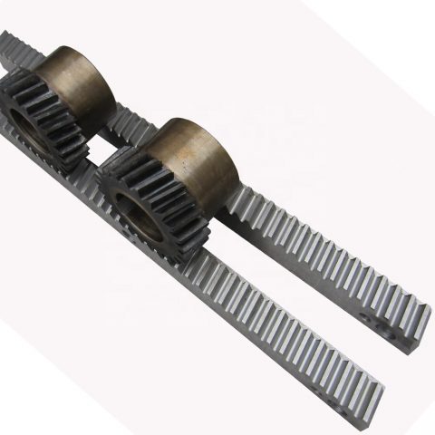 There are actually 4 eye(four bracket is light style) and six eyes(six brackets is heavy style).Every single piece of nylon gear rack with screw set
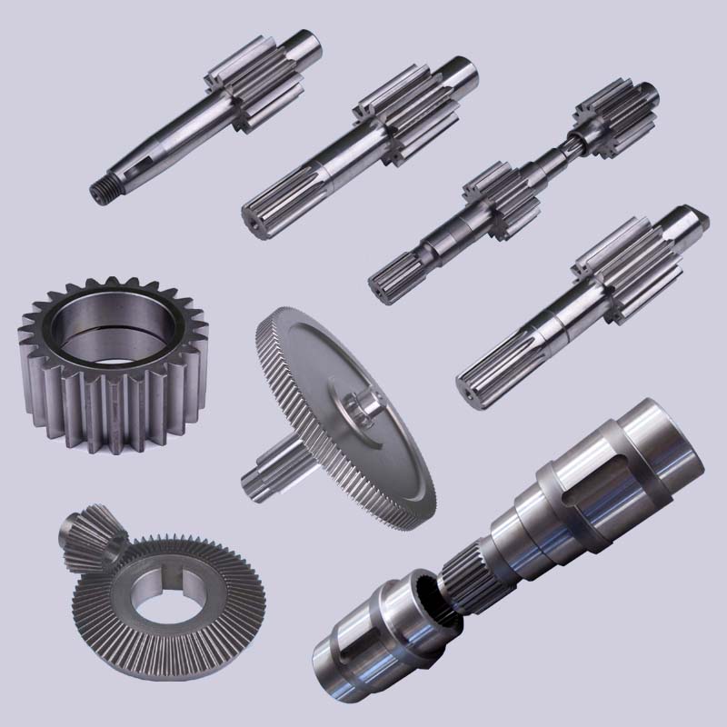 transmits movement and power in the gear pair. It is actually quite possibly the most extensively utilised mechanical transmission process in modern day products. Its transmission is a lot more exact, high efficiency, compact framework, dependable operation and lengthy service existence.
 coating and so forth.
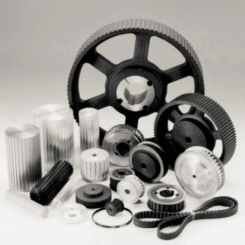 four) The bearing finish is constructed to guarantee the roller shaft and bearing is often firmly linked.
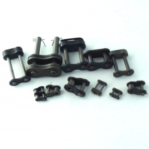 a straightforward, trustworthy, and productive signifies of electrical power transmission.